
Aerodynamically stable finless projectile

Inactive Publication Date: 2009-08-04
UNITED STATES OF AMERICA THE AS REPRESENTED BY THE SEC OF THE ARMY
View PDF27 Cites 19 Cited by
  • Summary
  • Abstract
  • Description
  • Claims
  • Application Information

AI Technical Summary

Benefits of technology

[0009]It is a goal of the present invention to provide a non-explosive, low cost finless projectile that prevents high velocity fragments from being dispersed in the vicinity of the launch weapon.
[0018]The aft projectile body of the finless projectile is also provided with a plurality of grooves to induce spin to the projectile once after muzzle launch. The spin enhances the aerodynamic stability of the projectile without the use of fins.

Problems solved by technology

The sabot shatters apart after muzzle launch into 9 or more pieces at high velocity, posing a hazard to personnel close to the weapon and potentially increasing collateral damage.
The shattering of the sabot after launch also creates an airflow disturbance that degrades the aiming accuracy of the projectile and degrades the muzzle velocity and ultimately the impact velocity.
Moreover, the complex assembly of a projectile with a sabot is relatively more costly to fabricate and manufacture.
The need for such a projectile has heretofore remained unsatisfied.

Method used


Image

  • Aerodynamically stable finless projectile
  • Aerodynamically stable finless projectile
  • Aerodynamically stable finless projectile

Examples


Embodiment Construction

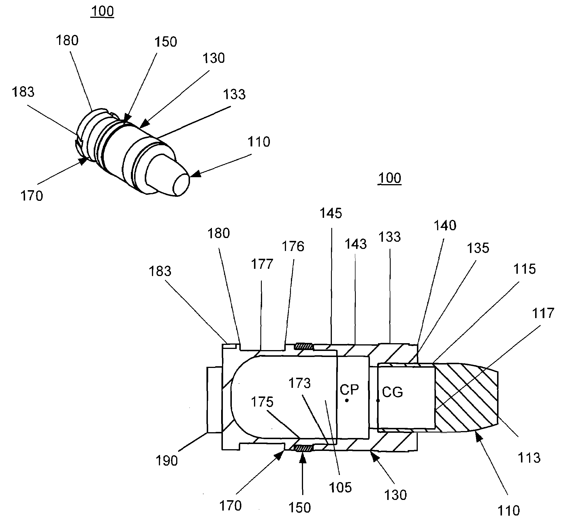
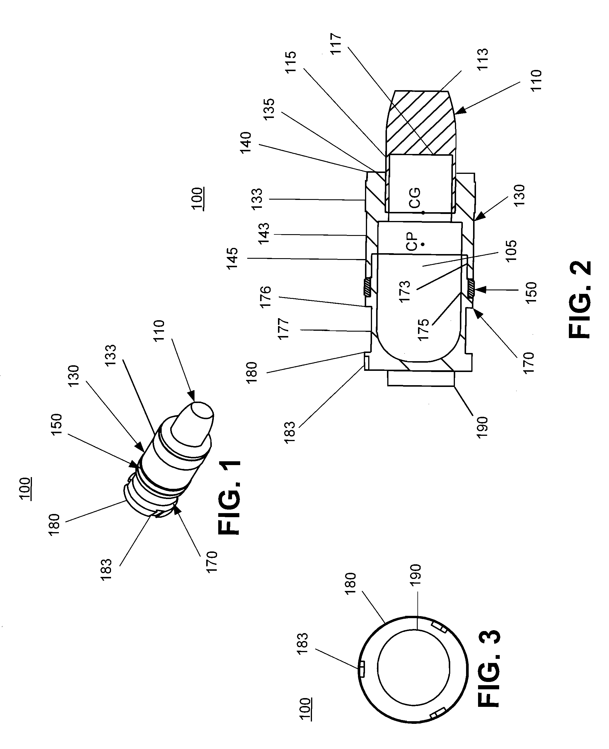
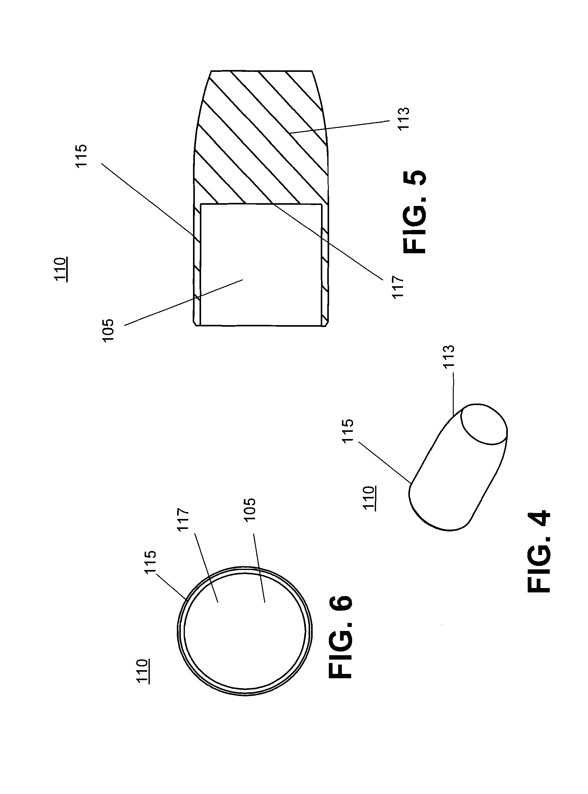
[0039]The finless projectile 100 can best be illustrated by viewing FIGS. 1-3 together. FIG. 1 is an isometric view of a finless projectile 100 of the present invention, shown without a sabot. FIG. 2 is a cross-sectional side view of the finless projectile. The projectile 100 generally includes a slug 110 that is disposed at a front portion or proximal end of the projectile 100. The projectile 100 further includes a forward projectile body 130, an obturator 150, an aft projectile body 170, and a pad 190 that is located at a distal end of the finless projectile. The projectile 100 includes a hollow core 105 provided for by the slug 110, the forward projectile body 130 and the aft projectile body 170.

[0040]The finless projectile can be fired, for example, from a 40 mm De-Armer rifle, for explosive ordnance disposal such as disarming a fuse, and breaking open a lock. The center of gravity (C.G.) of the projectile 100 is positioned forward of a center of pressure (C.P.). This configurat...


PUM


Abstract

A finless projectile provides improved ease of use, aerodynamics, muzzle velocity, drag, target, and excursion accuracy, structural integrity, terminal effectiveness and safety, at lower cost. The finless projectile includes a slug, a forward projectile body, an aft projectile body, an obturator, and a pad. The finless projectile is a full bore projectile that defines a hollow core, but does not include a sabot nor does it carry explosives. The finless projectile functions by kinetic energy transfer from the projectile to the target by deforming the target. The center of gravity of the finless projectile is forward of the center of pressure to provide static stability to the finless projectile.

Description

US GOVERNMENTAL INTEREST[0001]The inventions described herein may be manufactured, used and licensed by or for the U.S. Government for U.S. Government purposes.FIELD OF THE INVENTION[0002]The present invention generally relates to the field of munitions. More specifically, the present invention pertains to a non-explosive and aerodynamically stable finless projectile that is launched for explosive ordnance disposal.BACKGROUND OF THE INVENTION[0003]Terminal effectiveness is a primary criterion for projectiles. Depending on the function of the projectile, the impact velocity at the target primarily generally determines the terminal effectiveness of the projectiles, such as fin stabilized, sub-caliber armor piercing projectiles. The aerodynamic drag and related velocity decay during flight affect the impact velocity. In a conventional fin stabilized projectile, a shortening is made of the length of the acceleration transfer interface between sub-caliber projectile and discarding sabot....

Claims


Application Information

Patent Timeline
IPC IPC(8): F42B10/00F42B5/24F42B8/00
CPCF42B10/24F42B12/08F42B33/06F42B30/02F42B33/001F42B14/02
Inventor FARINA, ANTHONY P.WONG, BRIAN C.GILMAN, STEWART L.CHIN, DONALDWU, JOSEPH D.
Owner UNITED STATES OF AMERICA THE AS REPRESENTED BY THE SEC OF THE ARMY
Learn More