
Bicycle control device

a control device and bicycle technology, applied in the direction of steering devices, cycle equipment, transportation and packaging, etc., can solve the problems of inconvenient operation of brake levers and/or electrical switches, not suited to all types of handlebars, etc., and achieve the effect of simple and inexpensive manufacturing and assembly

Active Publication Date: 2009-07-28
SHIMANO INC
View PDF23 Cites 28 Cited by
  • Summary
  • Abstract
  • Description
  • Claims
  • Application Information

AI Technical Summary

Benefits of technology

The present invention is a bicycle control device that includes a brake lever and an electrical shift switch. The device can be easily mounted on the end of a handlebar and allows the rider to operate both the brake lever and the electrical shift switch with ease. The device is simple and inexpensive to manufacture and assemble. The technical effects of the invention include improved operability and ease of attachment to the bicycle handlebar.

Problems solved by technology

While these control devices work well, they are not suited for all types of handlebars.
In particular, when these control devices that include both a brake lever and an electrical switch are mounted to a free end of a handlebar, the brake lever and / or the electrical switch can be inconvenient to operate.

Method used


Image

  • Bicycle control device
  • Bicycle control device
  • Bicycle control device

Examples


Embodiment Construction

[0026]Selected embodiments of the present invention will now be explained with reference to the drawings. It will be apparent to those skilled in the art from this disclosure that the following descriptions of the embodiments of the present invention are provided for illustration only and not for the purpose of limiting the invention as defined by the appended claims and their equivalents.

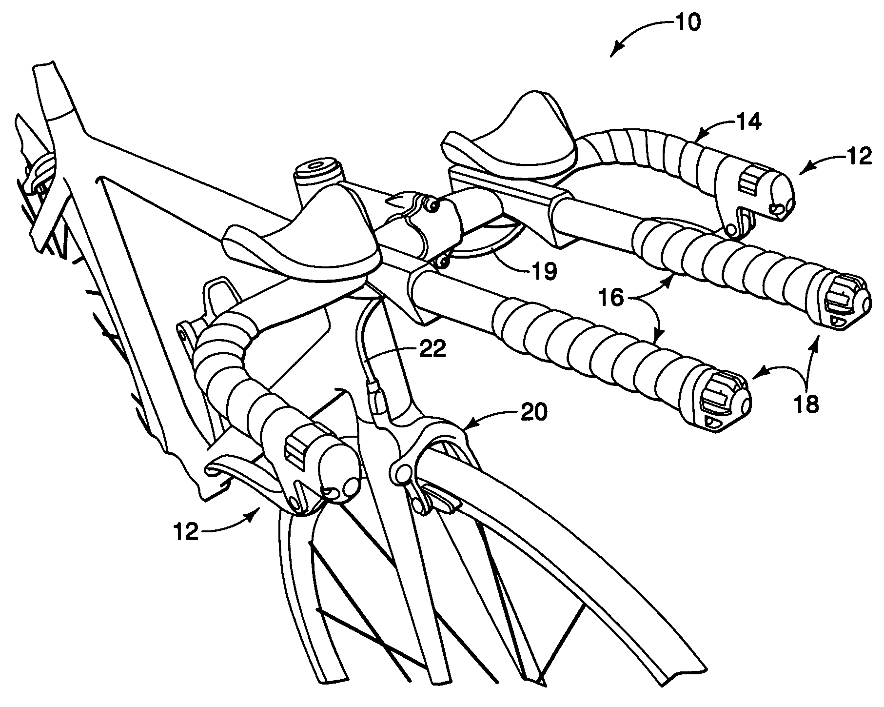
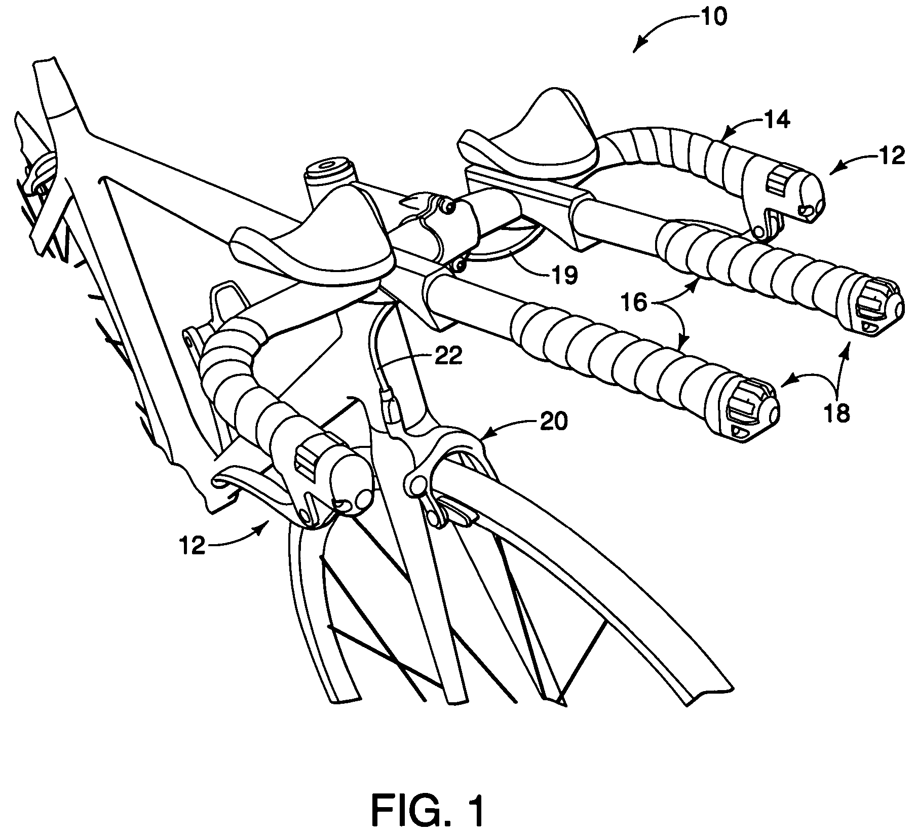
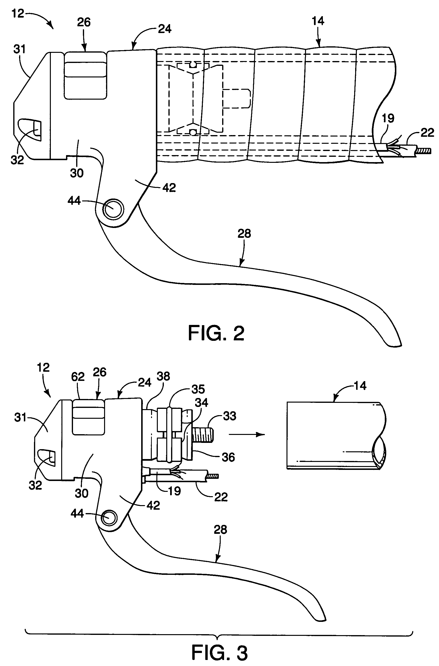
[0027]Referring initially to FIGS. 1 and 2, a bicycle 10 is illustrated with a pair of electrical shift / brake control devices 12 coupled to free ends of a bull horn handlebar 14 in accordance with the present invention. The bull horn handlebar 14 is also equipped with a pair of additional attachment bars 16 with each of the free ends of the attachment bars 16 having an electrical shift control device 18 mounted thereto. The electrical shift / brake control devices 12 and the additional electrical shift control devices 18 form parts of a brake and shift control system of the bicycle 10 in accordance w...


PUM


Abstract

A bicycle control device is provided that has a base member, an electrical shift control switch and a brake lever. The base member has a handlebar mounting portion configured to be fixedly mounted to a free end of a handlebar and an electrical switch housing portion extending longitudinally from the handlebar mounting portion such that a center axis of the free end of the handlebar extends longitudinally through the electrical switch housing portion when the base member is mounted to the free end of the handlebar. The electrical shift control switch is mounted to the electrical switch housing portion of the base member. The brake lever is pivotally attached to the base member to be selectively moved relative to the base member between a rest position and a braking position.

Description

BACKGROUND OF THE INVENTION[0001]1. Field of the Invention[0002]This invention generally relates to a bicycle control device. More specifically, the present invention relates to a bicycle control device that includes both an electrical shift control switch and a brake lever, which are configured to be mounted to the free end of a bicycle handlebar in an integrated manner.[0003]2. Background Information[0004]Bicycling is becoming an increasingly more popular form of recreation as well as a means of transportation. Moreover, bicycling has become a very popular competitive sport for both amateurs and professionals. Whether the bicycle is used for recreation, transportation or competition, the bicycle industry is constantly improving the various components of the bicycle, especially the bicycle control devices for shifting and braking.[0005]In the past, bicycle shifters were mechanically operated devices that were sometimes located near the brake levers of the bicycle. Thus, an operatin...

Claims


Application Information

Patent Timeline
Patent Type & Authority Patents(United States)
IPC IPC(8): B60K17/12
CPCB62K23/02B62K23/06B62M25/08B62M25/04Y10T74/20438Y10T74/2003B62K21/125
Inventor FUJII, KAZUHIRO
Owner SHIMANO INC
Learn More