Display assembly and method for its application

a technology of display assembly and assembly method, applied in the field of display assembly and method for its application, can solve the problem of large number of flagpoles that are not used, and achieve the effect of simple manner, pleasant design and pleasing appearan

Active Publication Date: 2009-07-21
HEMSSON
View PDF12 Cites 26 Cited by
  • Summary
  • Abstract
  • Description
  • Claims
  • Application Information

AI Technical Summary

Benefits of technology

[0011]In a particularly advantageous embodiment, illumination elements are provided, for instance on and / or onto and / or in a number of peripheral elements and / or connecting elements and / or a dressing. As a result, a particularly pleasant appearance is obtained, wherein the peripheral element or the peripheral elements together offer the advantage that in a simple manner, a pleasant design can be obtained.
[0012]Further, decorations can be provided on, in and / or onto a number of peripheral elements and / or connecting elements and / or a dressing. As a result of this too, a particularly pleasant appearance is obtained.
[0013]It is preferred that the dressing device is connected to the mast in a suitable manner, such that undesired movements are prevented. That is why it is preferred that a fastening device be provided with which the dressing device is secured to the mast at a distance from the upper part of the mast. This fastening device is preferably designed such that rotation of at least a part of the dressing device around the mast is possible while it preferably prevents horizontal and / or vertical movements. For instance, an annular fastening element can be provided which is fastened against the mast while a second, annular element can rotate therearound whereby vertical and horizontal movements are consequently prevented, as in a ball bearing or roller bearing. It is possible that only one fastening device is provided adjacent a bottom end of the dressing device but also, a series of fastening elements can be provided, for instance two or three or more, for instance one for each peripheral element. The or each fastening device is preferably divisible, such that it can be fastened around the mast in a simple manner.

Problems solved by technology

However, for large periods of time, a very large number of flagpoles stand unused.

Method used


Image

  • Display assembly and method for its application
  • Display assembly and method for its application
  • Display assembly and method for its application

Examples


Embodiment Construction

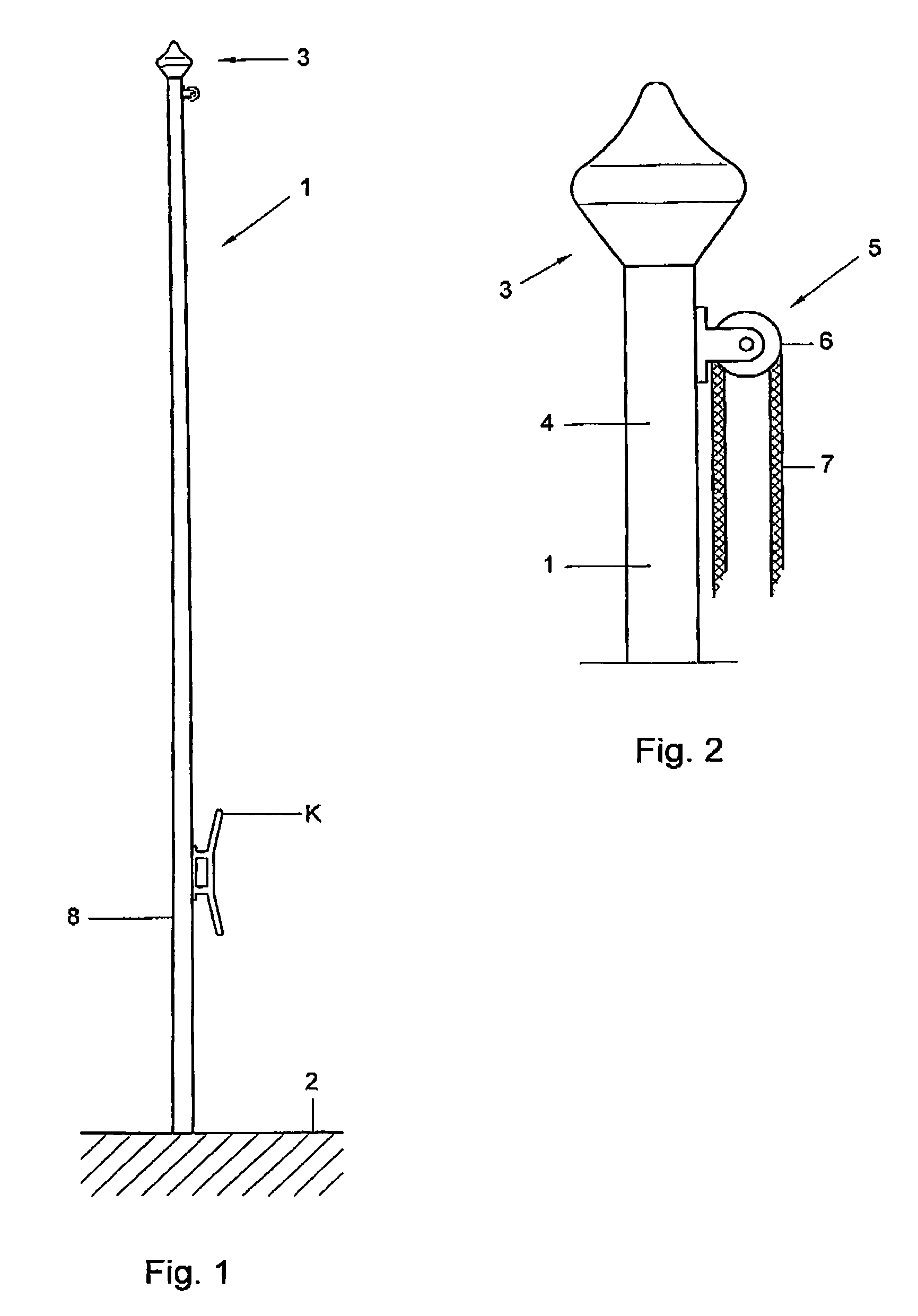
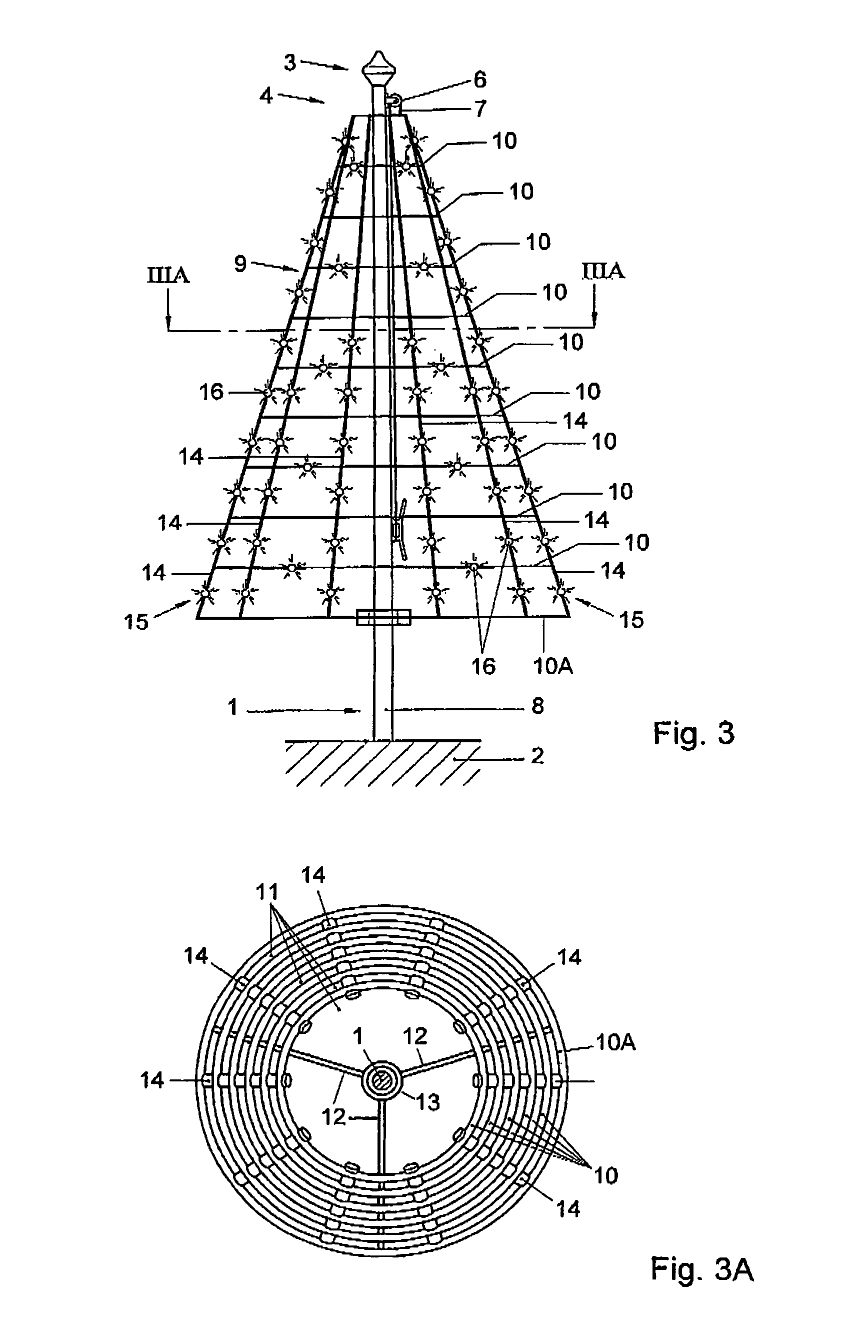
[0039]FIG. 1 shows a mast 1, arranged in vertical position in the ground 2. Adjacent the top end 3, at least in a top part 4, the mast is provided with a guiding element 5, for instance a pulley 6 as shown in FIG. 2, over which a rope 7 is guided, for instance a rope 7 with which, as a rule, a flag can be hoisted in the mast. The rope may be guided entirely outside the mast 1 but can also extend partly through the mast, so that, with the flag hoisted, the rope cannot be reached in a bottom part 8 of the mast 1 other than after opening of a hatch (not shown). In the exemplary embodiment shown, on the bottom part 8, a cleat K is provided to which the rope 7 can be secured.

[0040]In FIG. 3, a dressing device 9 is shown, suspended from the rope 7, at least from the mast 1. The dressing device 9 has a three-dimensional shape, in this embodiment substantially built up from a series of peripheral elements 10 in the form of substantially flat, annular elements as shown in FIG. 3A. In this em...


PUM


Abstract

An assembly including a mast dressing device that can be fastened to the mast, and a peripheral element or a series of mutually connected peripheral elements suspended from a top part of the mast. The dressing device is adapted to be hoisted by the mast, such that one peripheral element of the dressing device extends spirally around the mast, and/or a series of peripheral elements which are mutually connected by connecting elements are positioned in the vertical direction at a distance from each other.

Description

BACKGROUND OF THE INVENTION[0001]The present invention relates to an assembly of a mast and a dressing device to be fastened to this mast. The invention also relates in particular to such an assembly, comprising a flagpole and a dressing device.[0002]Flagpoles are known. As a rule, these are vertically raised poles having, near an upper part, suspension means for a flag. To that end, a rope may be provided through or along the mast, which is guided with the aid of a pulley or eyelet so that a flag attached to the rope can be hoisted and lowered. However, for large periods of time, a very large number of flagpoles stand unused.[0003]It is further known to set up decorative devices such as seasonal decorations, advertising elements and the like, for instance Christmas trees, illuminations of trees and houses and the like.SUMMARY OF THE INVENTION[0004]The object of the invention is an assembly with which a new use of a mast such as a flagpole is made possible. To that end, an assembly ...

Claims


Application Information

Patent Timeline
Patent Type & Authority Patents(United States)
IPC IPC(8): F21L14/00
CPCG09F17/00F21S4/001F21W2121/04A47G33/06F21S4/10Y10S362/806
Inventor GIERVELD, JOHAN
Owner HEMSSON
Why Eureka
Try Eureka