
Light emitting fishing lure which releases scent, emits sound and generates electricity

a technology of light-emitting lures and lures, which is applied in the field of artificial fishing lures, can solve the problems of recurring costs for replacement batteries or light-emitting sticks, damage to propeller blades, and place time limits on us

Inactive Publication Date: 2009-07-21
TURNER RANDAL SCOTT
View PDF177 Cites 30 Cited by
  • Summary
  • Abstract
  • Description
  • Claims
  • Application Information

AI Technical Summary

Benefits of technology

[0025]The lure body consist of a translucent durable plastic with all sides visible allowing the light from the diodes to illuminate off of said chrome paper insert then outward onto the outer fins, and of which lure assembly also has a connecting tail portion that is fastened by stainless steel non-magnetic bolts or like connections, and of which has a hollow chamber / reservoir within that can hold any type of scent attractant material such as oils or blood which are soaked and slowly released from a sponge which is inserted into said chamber or solid amino acid powders which dissolve slowly and releases said attracting scent into the water from holes located at the rear of said housing while being retrieved or trolled through the water, and of which also emits sound when said magnet rolls inside of the generators hollow circular inner chamber / cavity, and which sound may attracts fish to the lure.

Problems solved by technology

However, most electrically powered lures use batteries which need to be replaced frequently and chemically illuminated lures need replacement light sticks both of which place time limits on the use of the fishing lure and recurring costs for replacement batteries or light sticks.
The problems with all present generator lure inventions like that by Boharski U.S. Pat. No. 4,819,361 is that they require a shaft and bearing with a propeller or other apparatus mounted on the exterior portion of the lure, which pose a number of problems from water leakage in to the generator as the shaft or bearing wears out from usage, along with weeds and other vegetation within the lake, ocean or river, which can clog or tangle in the propeller, or the fishing line getting tangling within the propeller blades, or damaging the propeller blades if hit against any hard objects, rock, boat or stump when casting the lure or removing the lure from the water.

Method used


Image

  • Light emitting fishing lure which releases scent, emits sound and generates electricity
  • Light emitting fishing lure which releases scent, emits sound and generates electricity
  • Light emitting fishing lure which releases scent, emits sound and generates electricity

Examples


Embodiment Construction

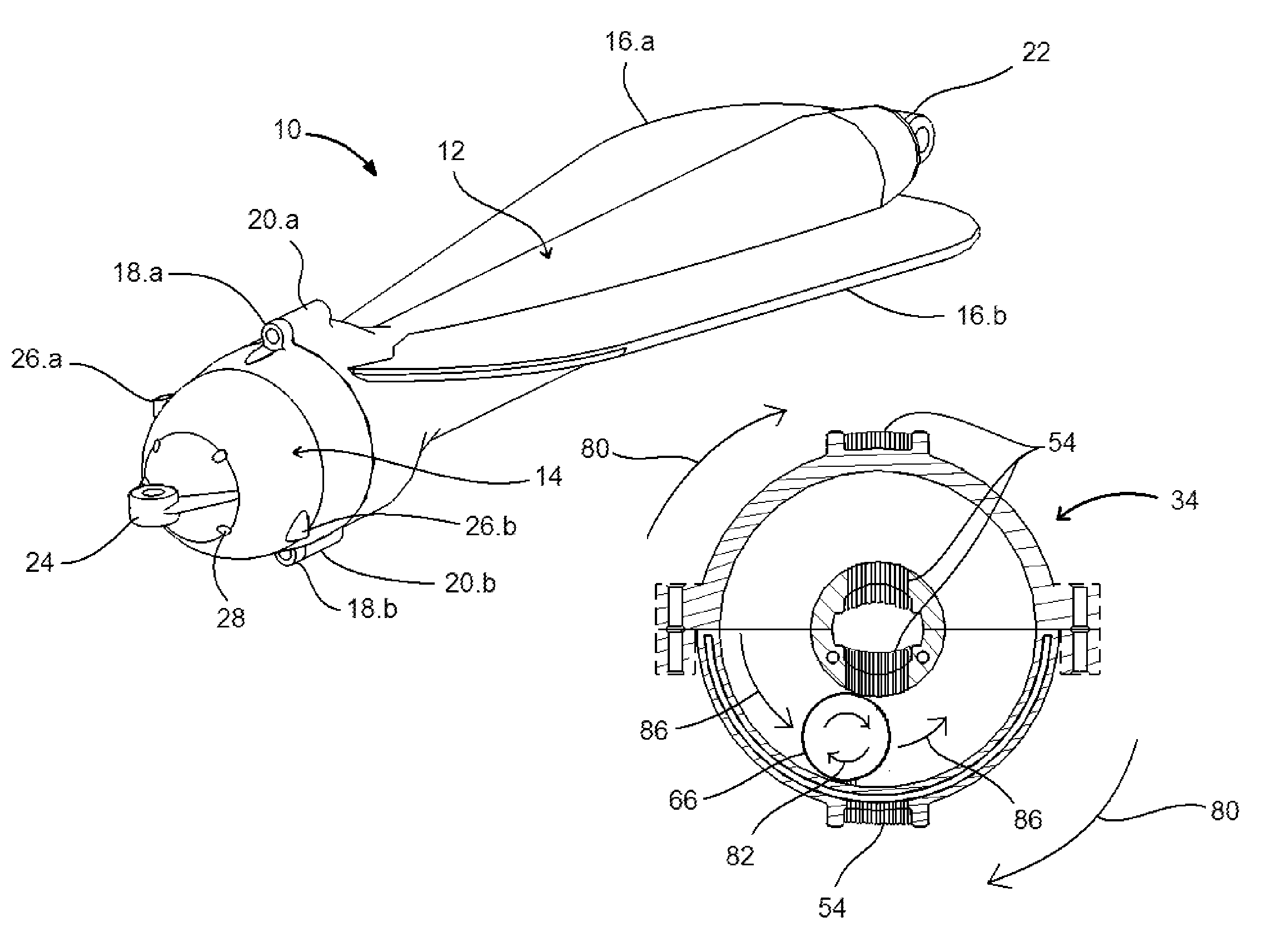
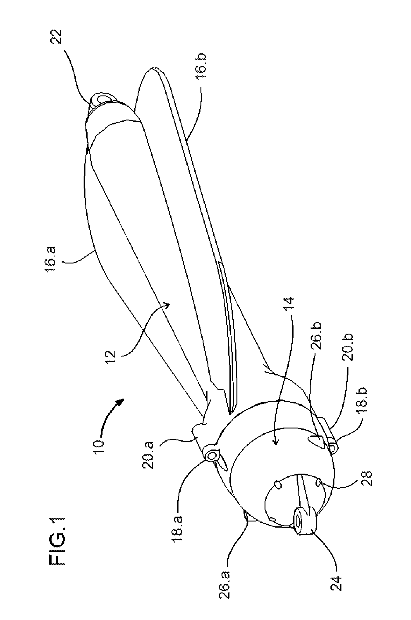
[0041]FIG. 1 shows a lure assembly 10 in accordance with the present invention.

[0042]As will be described in greater detail below, the lure is made up of two principal subassemblies, i.e., a conical nose segment 12, a tapered tail segment 14, The two are mounted together to form an elongate assembly, with first and second loops 22, 24 at the forward and rearward ends for attachment of a fishing line and a hook, in most instances with swivels at the attachment points.

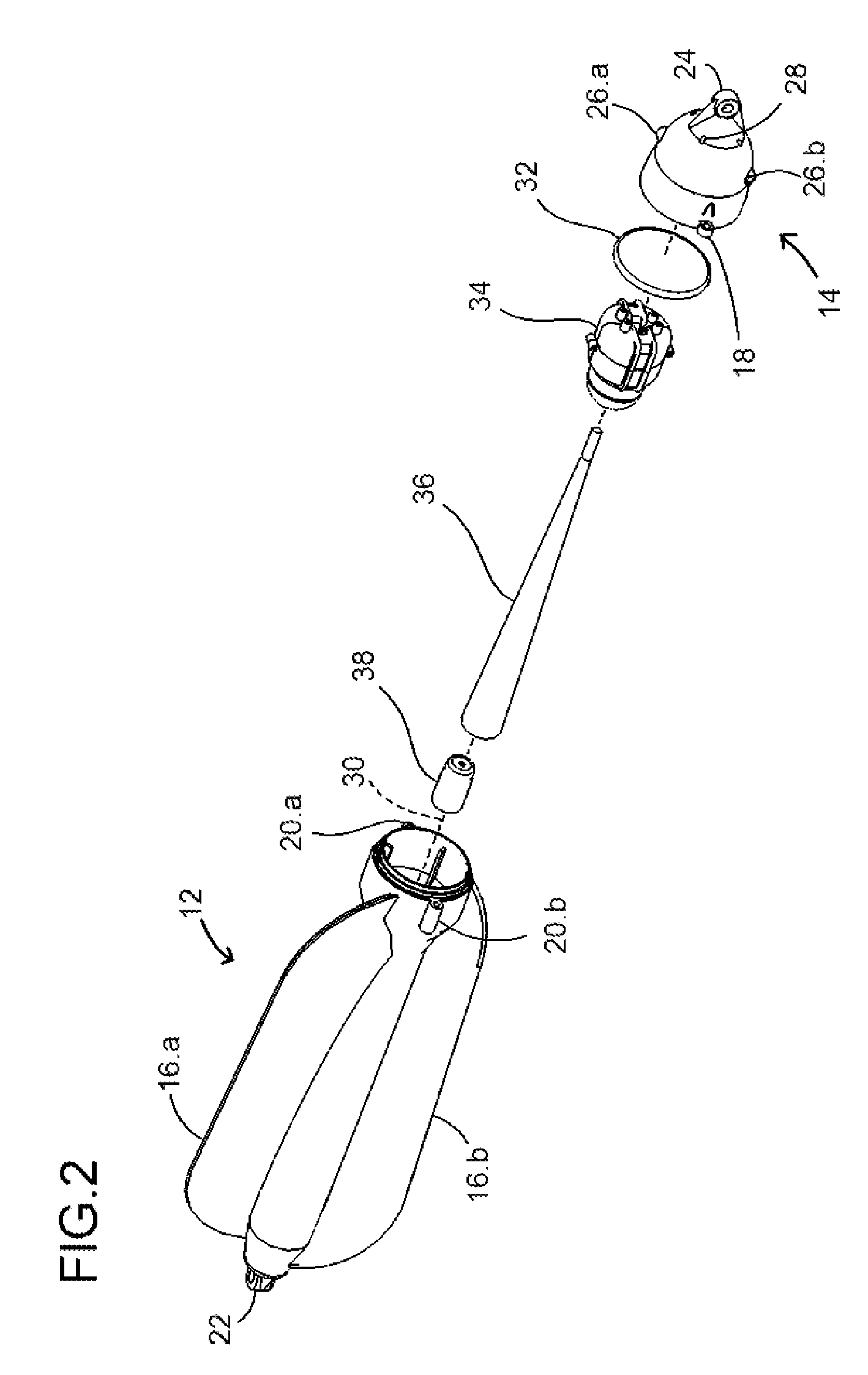
[0043]As can be seen more clearly in FIG. 2, the two segments detachably mount to one another along the common axis 30. In the preferred embodiment that is illustrated, the connections between the members are formed by sliding bolts through side holes 18.a 18.b which are located on each side of the tail segment 14 and screwing said bolts into threaded mounting holes 20.a 20.b which are located on each side of the nose segment 12 however, it will be understood that other forms of connections may be used, such as clamps wi...


PUM


Abstract

A fishing lure assembly utilizing a shaft less electric generator which does not require exterior moving components such as a propeller, shaft and bearing to activate the generator, The lure assembly is made up of two segments with a receiver for a weight, a chromed paper insert and a shaft less generator within the nose segment, and a reservoir for holding scent material in the tail segment. These segments are arranged along a longitudinal axis, with rotation being imparted to the assembly by angled fins on the nose segment; and of which rotating motion activates said generator to release electrical current which powers light emitting diodes, which in turn illuminates the fishing lure through a translucent body; along with a tail portion having a reservoir for inserting scented fish attractant, along with holes to allow water to flow into and exit out of the reservoir, which disperses scented fish attractant into the water slowly as the lure is trolled through the water, along with sound attractant caused by said generators magnet when said generator is rotating.

Description

CROSS REFERENCE TO RELATED APPLICATION[0001]This application claims the benefit of earlier filed provisional application # 60,862,608 filed: Oct. 24, 2006.BACKGROUND OF THE INVENTION[0002]1. Field of Invention[0003]The present invention relates generally to artificial fishing lures, and more particularly, to a fishing lure assembly capable of generating electricity without requiring exterior moving components, such as a shaft / bearing, and of which also utilizes scent and sound attractants from within the fishing lure / flasher body which produces light along with releasing scent and emitting sound from hollow chambers within said lure or flasher assemblies.[0004]2. Related Art[0005]It is well known that fish are attracted to light and has been used in the commercial fishing industry for over a decade with chemically illuminated lures or battery powered light emitting lures,[0006]It is also well know that fish are attracted by scent and is used in artificial fishing baits as well as ch...

Claims


Application Information

Patent Timeline
Patent Type & Authority Patents(United States)
IPC IPC(8): A01K85/01
CPCA01K85/12A01K85/01
Inventor TURNER, RANDAL SCOTT
Owner TURNER RANDAL SCOTT
Learn More