Optical microscope and spectrum measuring method
a spectrum measurement and optical microscope technology, applied in the field of optical microscope and spectrum measurement method, can solve the problems of difficult to change the laser light into a linear light beam having the same intensity, speckle noise, and the inability to uniformly illuminate the sample, etc., and achieve the effect of high accuracy measurement in a short period
- Summary
- Abstract
- Description
- Claims
- Application Information
AI Technical Summary
Benefits of technology
Problems solved by technology
Method used
Image
Examples
first embodiment
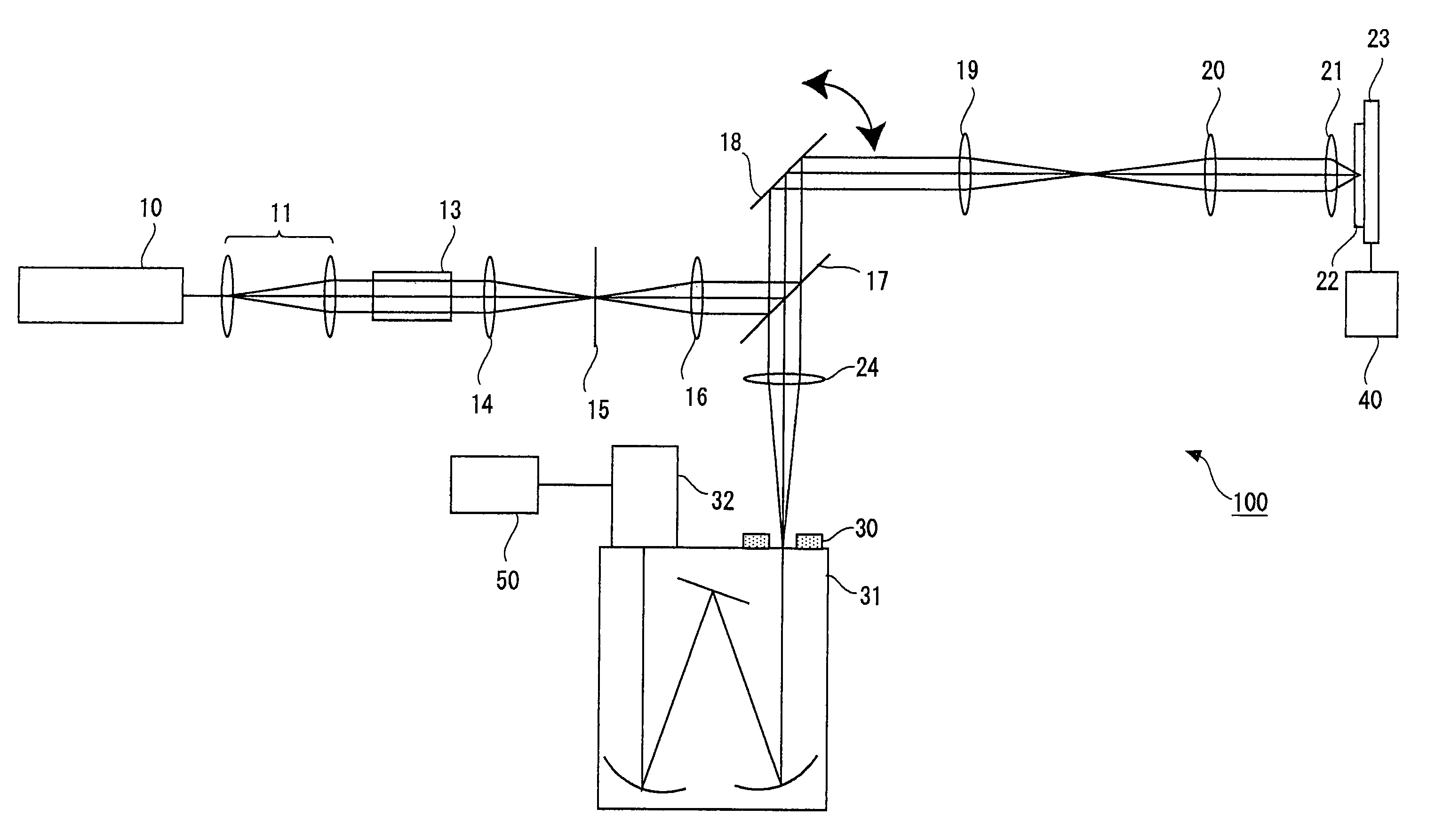
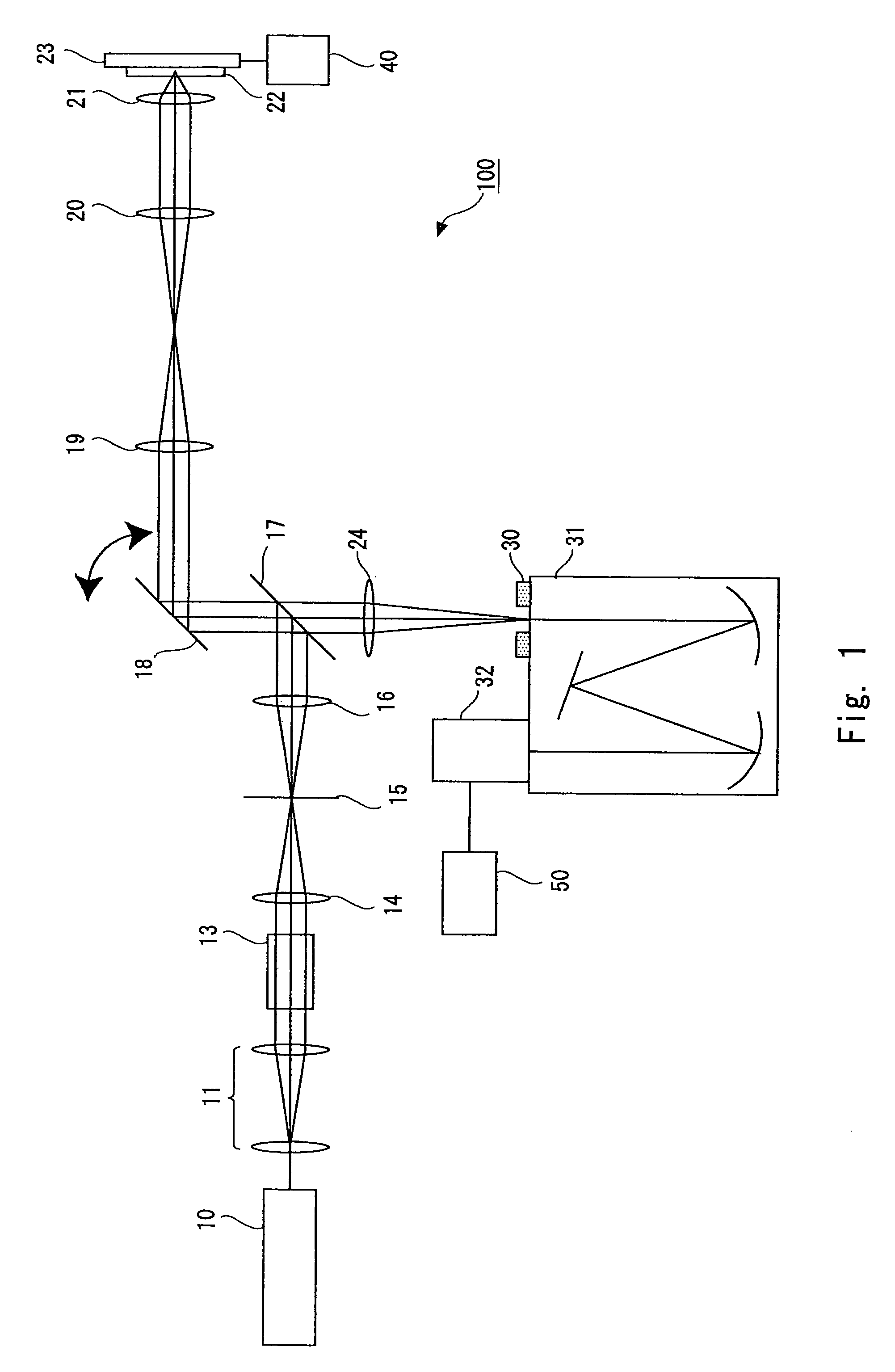
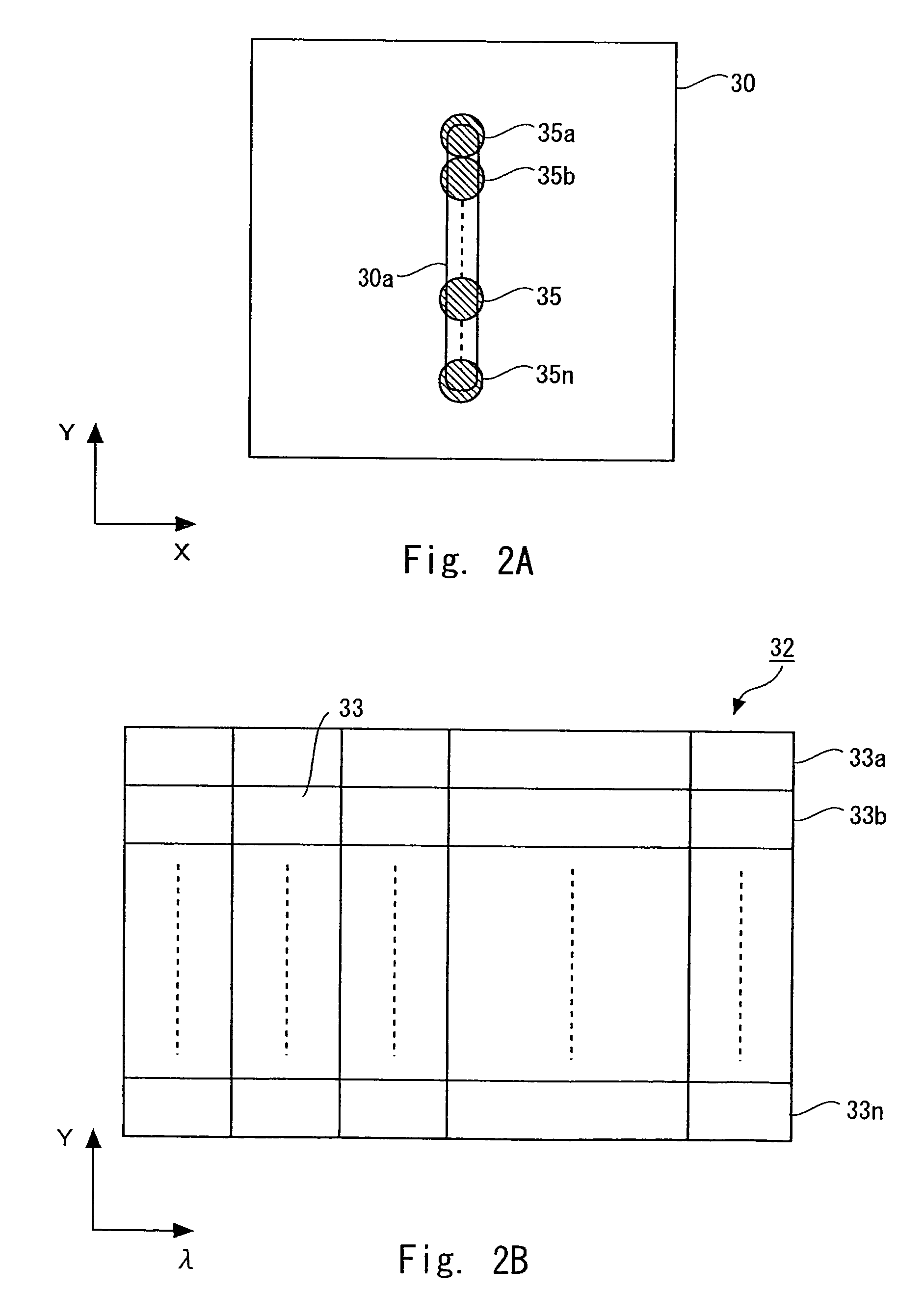
[0032]Referring to FIG. 1, an optical microscope according to a first embodiment of the present invention is described below. FIG. 1 schematically shows the structure of the optical microscope of this embodiment. An optical microscope 100 includes, as the structure for observing a sample 22, a laser light source 10, a beam expander 11, a Y-directional scanning unit 13, a lens 14, a diaphragm 15, a lens 16, a beam splitter 17, an X-directional scanning mirror 18, a lens 19, lens 20, an objective lens 21, a stage 23, a lens 24, a spectroscope 31, a detector 32, a stage driver 40, and a processor 50. The spectroscope 31 is provided with an entrance slit 30 on an incidence side.
[0033]The optical microscope 100 is a Raman microscope. The optical microscope allows light beam from the laser light source 10 to enter the sample 22 and detects Raman scattered light from the sample 22 with the detector 32. Further, the spectroscope 31 diffuses the Raman scattered light, and thus Raman spectrum...
second embodiment
[0072]Referring to FIG. 7, an optical microscope according to a second embodiment of the present invention is described next. FIG. 7 shows the structure of the optical microscope of the second embodiment. Incidentally, the optical microscope of this embodiment includes a cylindrical lens 51 in addition to the components of the optical microscope of the first embodiment. The cylindrical lens 51 is provided downstream of the lens 14. Incidentally, the basic structure of the optical microscope of this embodiment is the same as that of the first embodiment, so its description is omitted here. That is, components other than the cylindrical lens 51 are the same as those of the first embodiment.
[0073]As shown in FIG. 7, the cylindrical lens 51 is provided between the lens 14 and the diaphragm 15. The cylindrical lens 51 is a concave lens. The cylindrical lens 51 cancels out light components refracted in the Y direction by the lens 14 as a convex lens. Thus, the beam spot of the laser light...
third embodiment
[0076]Referring to FIG. 8, the structure of an optical microscope according to a third embodiment of the present invention is described next. FIG. 8 shows the structure of the optical microscope of the third embodiment. Incidentally, the optical microscope of this embodiment includes a container 61 in addition to the components of the optical microscope of the first embodiment. The container 61 is provided between the lens 19 and the lens 20. Incidentally, the basis structure of the optical microscope of this embodiment is the same as that of the first embodiment, and its description is omitted here. That is, components other than the container 61 are the same as those of the first embodiment.
[0077]The container 61 is, for example, a vacuum container. That is, the inside of the container 61 is kept under vacuum. The container 61 is provided at a position where the lens 19 condenses the laser light. That is, the container 61 is provided at an image formation plane of the lens 19. Win...
PUM
 Abstract
Description
Claims
Application Information
 - R&D
- Intellectual Property
- Life Sciences
- Materials
- Tech Scout
- Unparalleled Data Quality
- Higher Quality Content
- 60% Fewer Hallucinations
Browse by: Latest US Patents, China's latest patents, Technical Efficacy Thesaurus, Application Domain, Technology Topic, Popular Technical Reports.
© 2025 PatSnap. All rights reserved.Legal|Privacy policy|Modern Slavery Act Transparency Statement|Sitemap|About US| Contact US: help@patsnap.com


