Protective device with an auxiliary switch

a protection device and auxiliary switch technology, applied in the direction of circuit-breaking switches, emergency protective arrangements for limiting excess voltage/current, coupling device connections, etc., can solve the problems of electrical wiring system certain types of faults, electrical connectivity breakage, electrical shock hazards, etc., to improve reliability.

Active Publication Date: 2009-06-30
PASS SEYMOUR
View PDF9 Cites 20 Cited by
  • Summary
  • Abstract
  • Description
  • Claims
  • Application Information

AI Technical Summary

Benefits of technology

[0015]The present invention is directed to a protective device that denies power to an electric circuit when the device loses its protective functionality. In particular, the protective device of the present invention denies power to the protected circuit when the SCR is experiencing an end of life condition. The present invention accomplishes the power denial using an auxiliary switch designed to have an improved reliability.

Problems solved by technology

However, certain types of faults have been known to occur in electrical wiring systems.
The circuit interrupter provides power to the load terminals under normal conditions, but breaks electrical connectivity when the protective device detects a fault condition in the load circuit.
A ground fault occurs when a current carrying (hot) conductor creates an unintended current path to ground.
The unintended current path represents an electrical shock hazard.
Ground faults, as well as arc faults, may also result in fire.
This type of fault may occur when the load neutral terminal, or a conductor connected to the load neutral terminal, becomes grounded.
While this condition does not represent an immediate shock hazard, it may lead to serious hazard.
Therefore, if a double-fault condition occurs, i.e., if the user comes into contact with a hot conductor (the first fault) when simultaneously contacting a neutral conductor that has been grounded on the load side (the second fault), the user may experience serious injury or death.
However, a protective device, like all electrical devices, has a limited life expectancy.
This poses a problem in that when the device has reached end of life, the user may not be protected from the fault condition.
End of life failure modes include failure of device circuitry, the circuit interrupter that opens (trips) the GFCI interrupting contacts, the relay solenoid that opens the GFCI interrupting contacts, and / or the solenoid switching device.
An end of life failure mode can result in the protective device not protecting the user from the faults referred to above.
One drawback to this approach lies in the fact that if the user fails to use the test button, the user will not know if the device is functional.

Method used


Image

  • Protective device with an auxiliary switch
  • Protective device with an auxiliary switch
  • Protective device with an auxiliary switch

Examples


Embodiment Construction

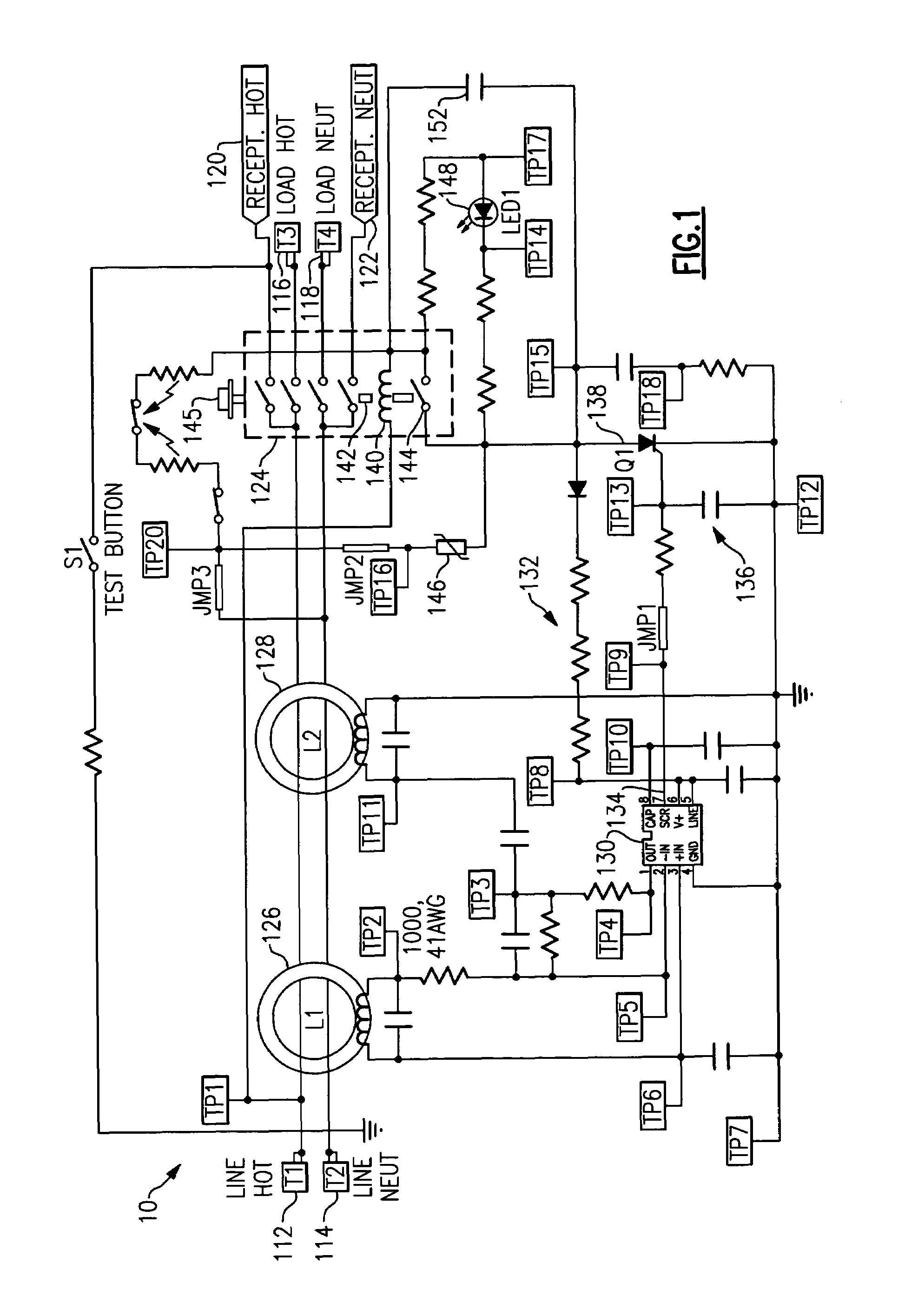
[0031]Reference will now be made in detail to the present exemplary embodiments of the invention, examples of which are illustrated in the accompanying drawings. Wherever possible, the same reference numbers will be used throughout the drawings to refer to the same or like parts. An exemplary embodiment of the protective device of the present invention is shown in FIG. 1, and is designated generally throughout by reference numeral 10.

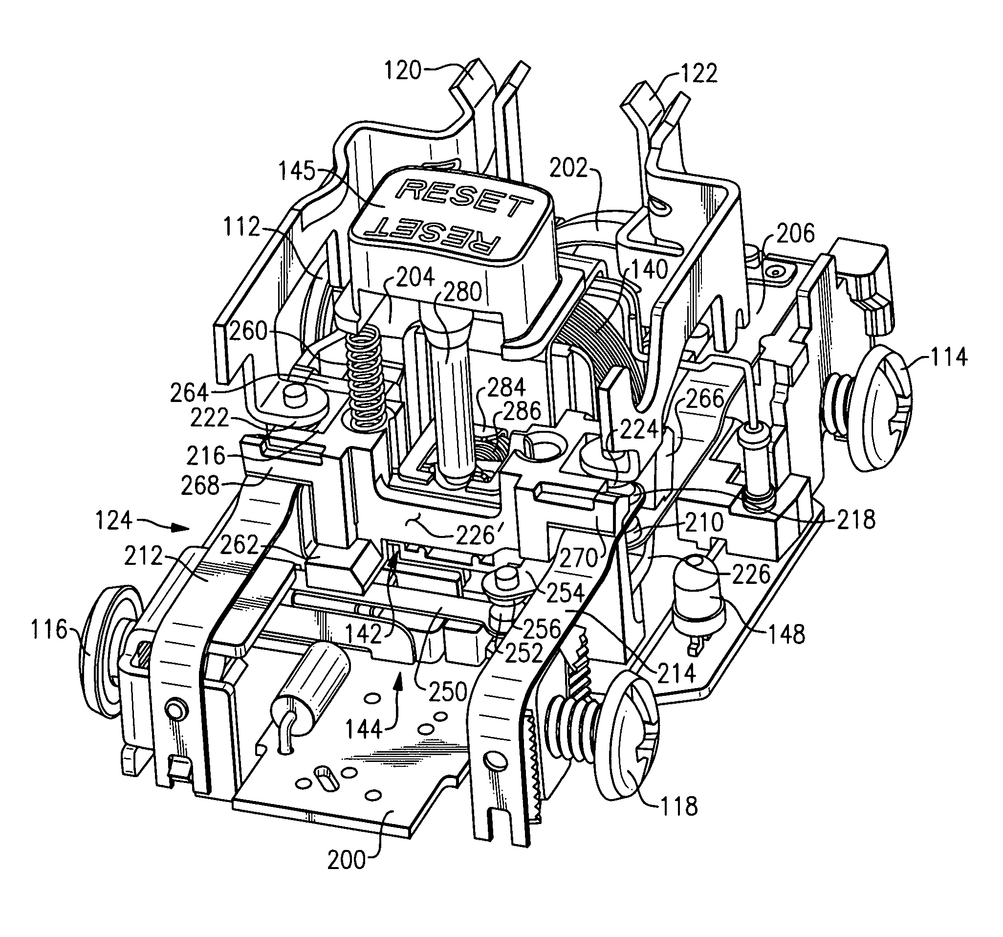
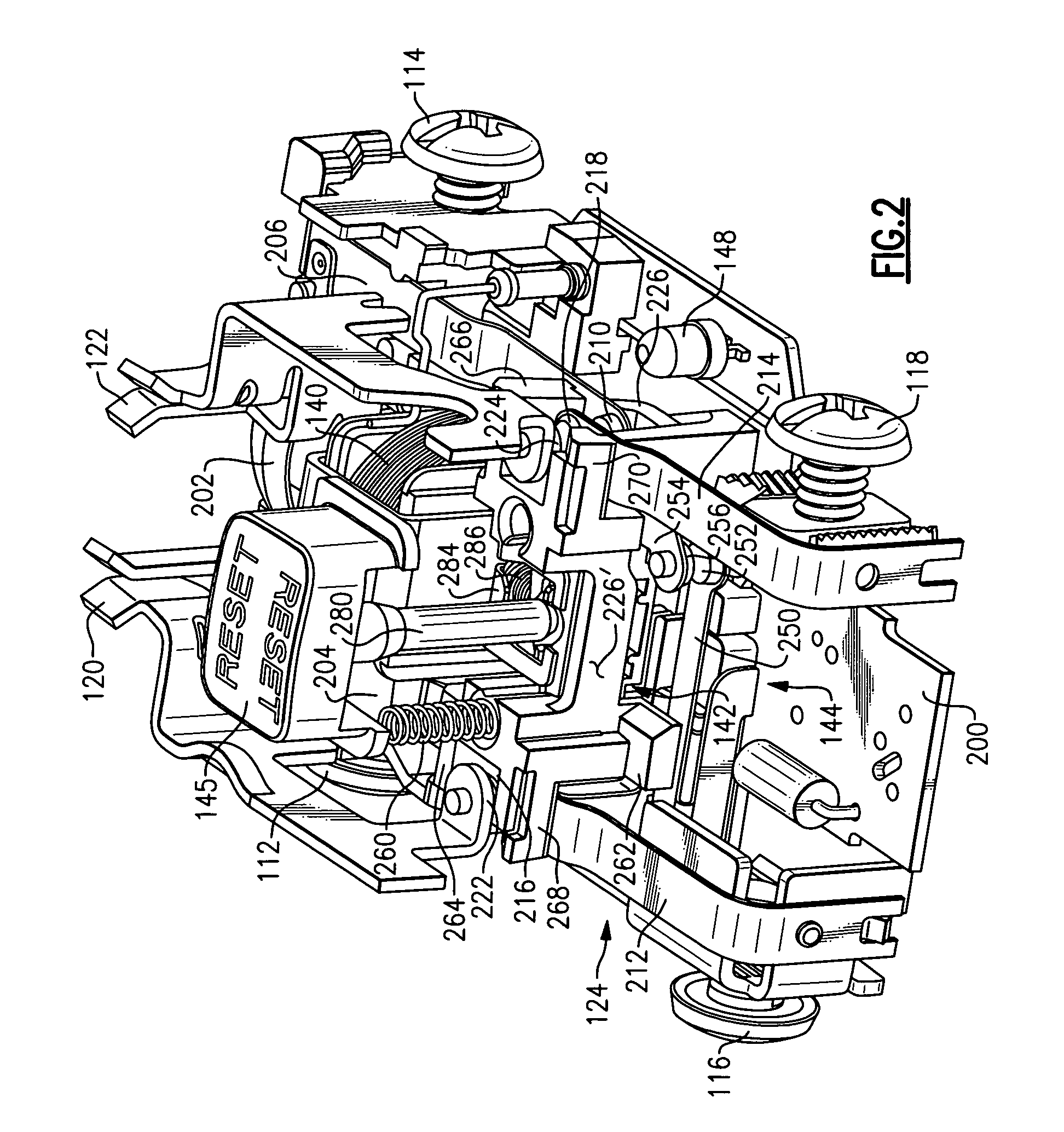
[0032]As embodied herein, and depicted in FIG. 1, a schematic of a circuit protection device 10 in accordance with an embodiment of the present invention is disclosed. GFCI 10 includes ground fault interrupter circuitry. Device 10 includes line terminals 112, 114, load terminals 116, 118, and receptacle terminals 120, 122. Load terminals 116, 118 may also be referred to as feed-through terminals. As noted above, these terminals may be connected to wiring configured to provide power to downstream receptacles or switches. Receptacle load terminals 120,122...


PUM


Abstract

The present invention is directed to a protective device that includes a plurality of line terminals, a plurality of load terminals, and a fault detection assembly coupled to the plurality of line terminals. The fault detection circuit is configured to provide a fault detection output in response to detecting a fault condition. A circuit interrupter is coupled between the plurality of line terminals and the plurality of load terminals. The circuit interrupter includes a first set of contacts, the first set of contacts being configured to close to establish at least one electrically continuous path between the plurality of line terminals and the plurality of load terminals in a reset state. The first set of contacts are also configured to open to disconnect the at least one electrically continuous path in response to the fault detection output to enter a tripped state. An auxiliary switch is coupled to the fault detection assembly. The auxiliary switch includes a second set of contacts configured to decouple at least a portion of the fault detection assembly from a source of electrical power in the tripped state. A latch assembly is coupled to the circuit interrupter. The latch assembly includes a first latch block mechanism configured to close the first set of contacts in the reset state and a second latch block mechanism configured to open the second set of contacts in the tripped state.

Description

CROSS-REFERENCE TO RELATED APPLICATIONS[0001]This is a continuation-in-part of U.S. patent application Ser. No. 10 / 901,688 filed on Jul. 29, 2004, now U.S. Pat. No. 7,312,782 the content of which is relied upon and incorporated herein by reference in its entirety, and the benefit of priority under 35 U.S.C. §120 is hereby claimed.BACKGROUND OF THE INVENTION[0002]1. Field of the Invention[0003]The present invention relates generally to electrical wiring devices, and particularly to electrical wiring devices including protective features.[0004]2. Technical Background[0005]AC power is coupled to an electrical distribution system at a breaker panel. The breaker panel is disposed within a residence, commercial building or some other such facility. The breaker panel distributes AC power to one or more branch electric circuits installed in the structure. The electric circuits may typically include one or more receptacle outlets and may further transmit AC power to one or more electrically ...

Claims


Application Information

Patent Timeline
IPC IPC(8): H01H73/02
CPCH01H3/001H01H83/04H01R13/7135H01H2071/044
Inventor WEEKS, RICHARDSAVICKI, JR., GERALD R.
Owner PASS SEYMOUR
Why Eureka
Try Eureka