
Electromagnetic testing of an enclosure or cavity using a discrete frequency stir method

a technology of discrete frequency and enclosure, applied in the direction of resistance/reactance/impedence, measurement devices, instruments, etc., can solve the problems of time-consuming or equipment-intensive field mapping locations inside the enclosure, high field randomness and high variability, and achieve simplified test setup, reduced test time, and high accuracy.

Active Publication Date: 2009-06-30
THE BOEING CO
View PDF12 Cites 16 Cited by
  • Summary
  • Abstract
  • Description
  • Claims
  • Application Information

AI Technical Summary

Benefits of technology

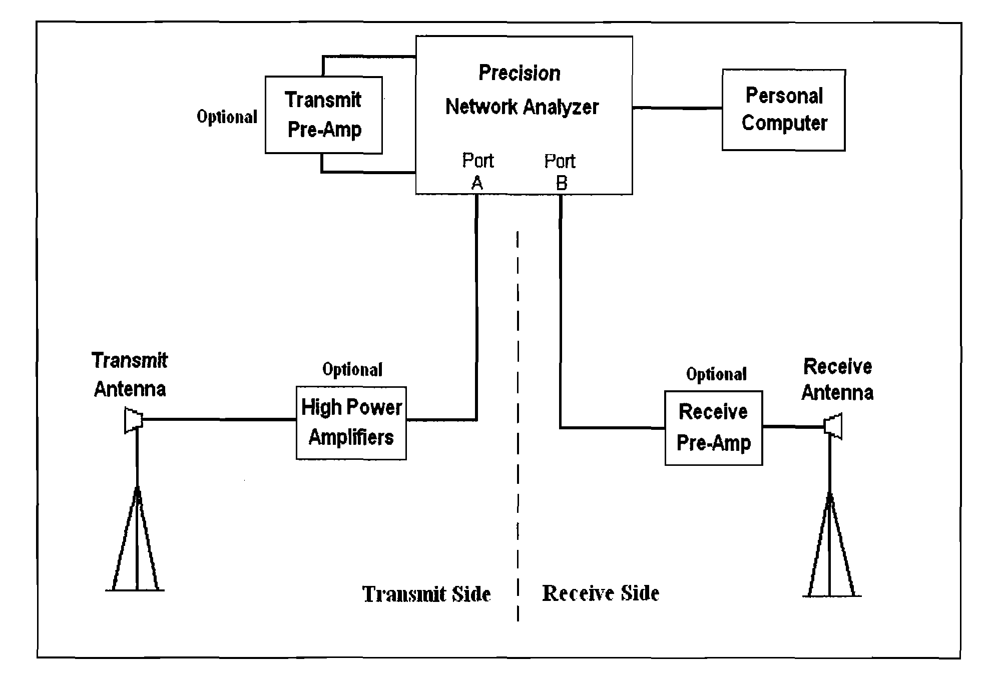
The present invention provides a method for improved mode stir testing of enclosures or cavities. This method uses a discrete frequency stir (DFS) approach, which involves exciting the enclosure or cavity with a short duration, continuous wave, radiated source where the continuous wave frequency is stepped in small frequency steps across a frequency range of interest. The frequency steps are selected to be at least slightly larger than the resonant mode bandwidth associated with the given enclosure or cavity in order to provide statistically independent measurements. A statistical evaluation of the measured field is then performed over this stirring bandwidth. The DFS method is particularly suitable for accurately measuring the average field level within an electrically large, "lossless" enclosure and determining the peak field level statistically from the measured data. The DFS measurement method is applicable to aircraft shielding measurements, RF propagation measurements, component level shielding measurements, electrical properties extraction for electrically large and complex structures, and radiated immunity testing. The DFS method offers a simplified test setup, reduced test time, and improved dynamic range as compared to other mode stir methods. It also allows for statistical analysis of the measured field and is faster than traditional frequency mode stir.

Problems solved by technology

A key problem associated with the measurement of the electromagnetic field inside an electrically large and relatively lossless enclosure is that the field is random and highly variable (with field variations from point to point inside the enclosure).
As field mapping locations inside the enclosure would be too time consuming or too equipment intensive, mode stir methods have been widely used for statistical measurement of electromagnetic characteristics of an enclosure.
Mechanical stirring suffers from being time intensive and limited by how well the paddle wheel is designed and used to stir the field.
The paddle wheel also adds a level of complexity to the test setup, since its rotation must be synchronized with the measurement equipment and any other paddle wheels used in the test setup.
The traditional frequency stir method has limitations associated with the loss of statistical data components and the complexity and performance of the measurement equipment.
As a result, a statistical analysis of the contributing field levels cannot be made to check the measurement against prevailing mode stir theory.
Also, since the excitation source for the traditional frequency stir method is a band-limited noise signal superimposed on a single frequency sine wave, the test equipment setup is more complex, requiring more pieces of equipment including a separate signal generator and receiver.
This makes it more difficult to move the measurement equipment for remote area tests.
Further, the actual generation of a well defined band-limited noise signal can be problematic (especially at higher frequencies, i.e., above 10 GHz).
Since the measurement is a broadband measurement, this technique suffers more than the others from dynamic range limitations and possible noise interference (when used at open area test sites).

Method used


Image

  • Electromagnetic testing of an enclosure or cavity using a discrete frequency stir method
  • Electromagnetic testing of an enclosure or cavity using a discrete frequency stir method
  • Electromagnetic testing of an enclosure or cavity using a discrete frequency stir method

Examples


Embodiment Construction

[0032]Background: Mode Stir Introduction

[0033]Mode stir methods are used to generate statistically uniform fields within electrically large, relatively lossless enclosures or cavities for conducting electromagnetic testing. Mode stir techniques have been used extensively within the reverberation chamber environment for radiated immunity and emissions testing of electrical equipment, as well as shielding effectiveness measurements of screens, windows, cable shields, etc. Reverberation chambers are specific instances of an electrically large, high Q cavity that support a large number of normally distributed eigenmodes (TE and TM modes) with zero mean and equal variances. The large number of modes combine (in a vector summation sense) to generate a randomized electromagnetic environment within the cavity. Perturbation of this modal structure, commonly called mode-stirring, by changing either the geometry of the cavity (mechanical mode stir) or the frequency of the excitation source (el...


PUM


Abstract

The “discrete frequency stir” (DFS) method provides improved mode stir testing of electromagnetic characteristics of an enclosure / cavity. Adequate sampling of the electric field inside the enclosure / cavity is provided by electronic perturbation or “stirring” of the field with a short duration, continuous wave, radiated source where the wave frequency is stepped in small steps across a frequency range of interest. The frequency steps are selected to be at least slightly larger than the resonant mode bandwidth associated with the given enclosure / cavity in order to provide statistically independent measurements. A stirring bandwidth is selected to encompass a statistically significant number of these measurement samples while maintaining adequate frequency resolution. A statistical evaluation of the measured field is then performed over this stirring bandwidth. For example, the average field level at a given frequency is determined by averaging over the samples contained within the stirring bandwidth when centered on that frequency.

Description

TECHNICAL FIELD[0001]The present invention relates generally to electromagnetic testing of an enclosure or cavity for the determination of select electrical characteristics (e.g. RF shielding characteristics or RF propagation characteristics). More particularly, the present invention is related to an alternative and, in some respects, improved mode stir measurement technique for the performance of such tests.BACKGROUND OF THE INVENTION[0002]A key problem associated with the measurement of the electromagnetic field inside an electrically large and relatively lossless enclosure is that the field is random and highly variable (with field variations from point to point inside the enclosure). However, the field is also considered to be statistically uniform, for example, the average measured in one general location of the enclosure will be approximately the same as the average measured in another general location within the same enclosure. Because the field is random and highly variable,...

Claims


Application Information

Patent Timeline
Patent Type & Authority Patents(United States)
IPC IPC(8): G01R27/28
CPCG01N27/72
Inventor HORTON, NATHANIEL T.LEWIS, DENNIS M.
Owner THE BOEING CO
Learn More