
Apparatus and method for identifying a system under test

a technology of system information and test script, applied in the field of data processing systems, can solve the problems of unduly burdensome task of continually updating the system information stored in test scripts, and difficult task of tracking information associated with each of the different computer systems

Inactive Publication Date: 2009-06-23
SAP AG
View PDF5 Cites 51 Cited by
  • Summary
  • Abstract
  • Description
  • Claims
  • Application Information

AI Technical Summary

Benefits of technology

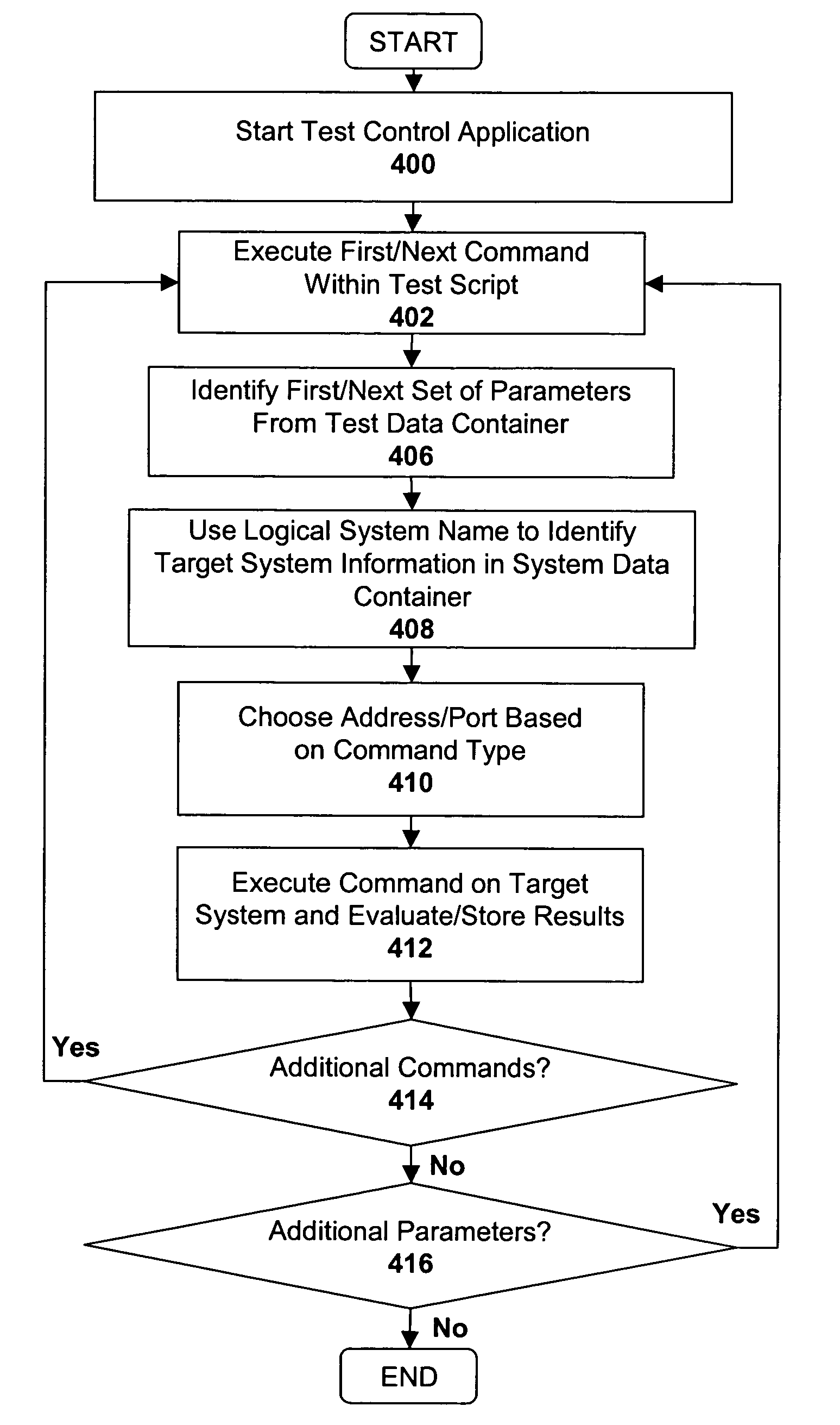
The patent describes a system and method for testing an application on a target system. The target system is assigned a unique name that is used by a test script to refer to it. This name is associated with different communication channels within a system data container. During the testing process, a specific communication channel is selected based on the type of command in the test script that references the target system. This helps to ensure that the test is run on the correct channel and reduces the likelihood of errors or failures during the testing process.

Problems solved by technology

In a large enterprise network, tracking information associated with each of the different computer systems can be a difficult task.
Continually updating the system information stored within test scripts is an unduly burdensome task, particularly in a large enterprise network which may be comprised of hundreds of different target computer systems.

Method used


Image

  • Apparatus and method for identifying a system under test
  • Apparatus and method for identifying a system under test
  • Apparatus and method for identifying a system under test

Examples


Embodiment Construction

[0014]Throughout the description, for the purposes of explanation, numerous specific details are set forth in order to provide a thorough understanding of the present invention. It will be apparent, however, to one skilled in the art that the present invention may be practiced without some of these specific details. In other instances, well-known structures and devices are shown in block diagram form to avoid obscuring the underlying principles of the present invention.

EMBODIMENTS OF THE INVENTION

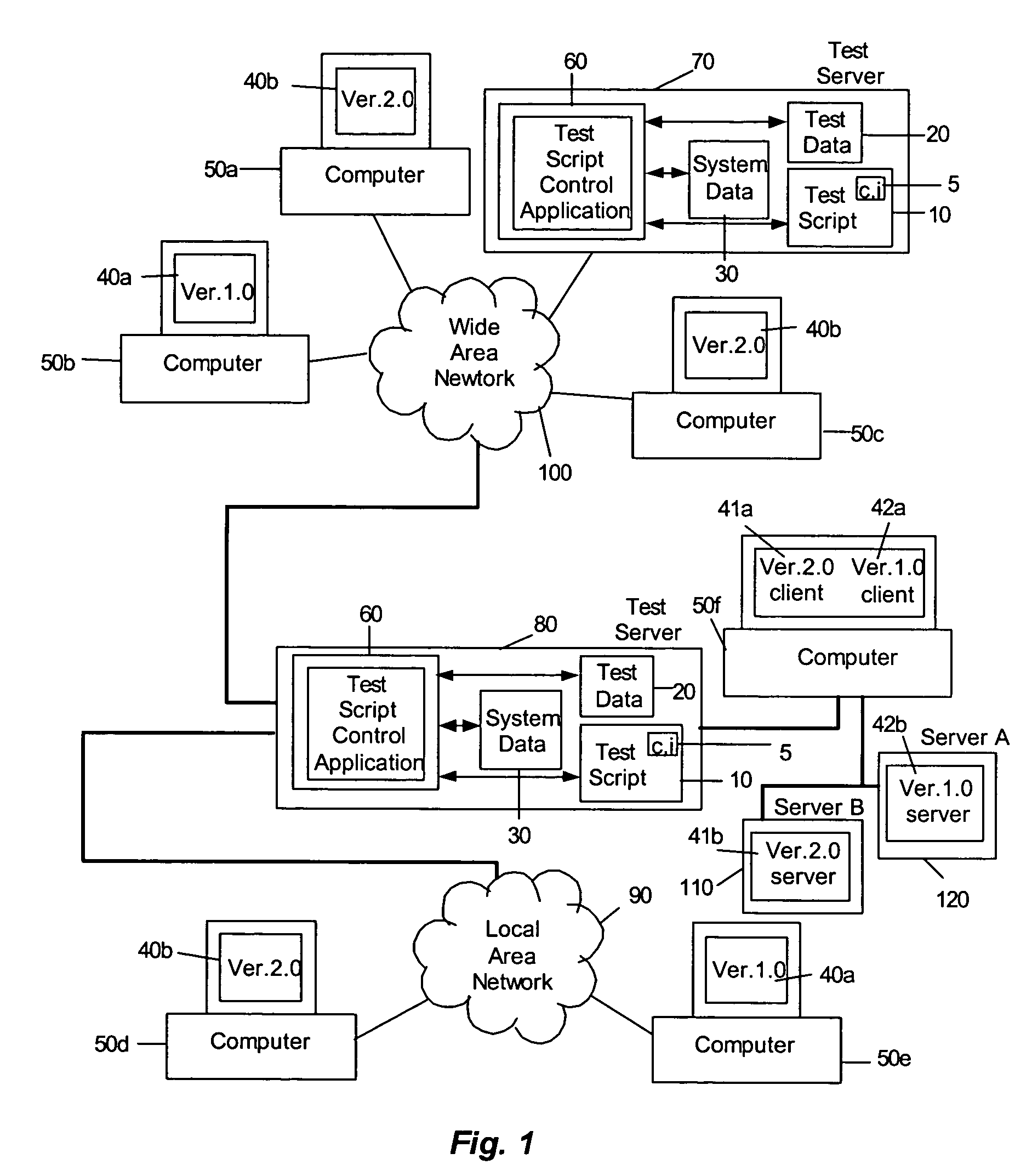
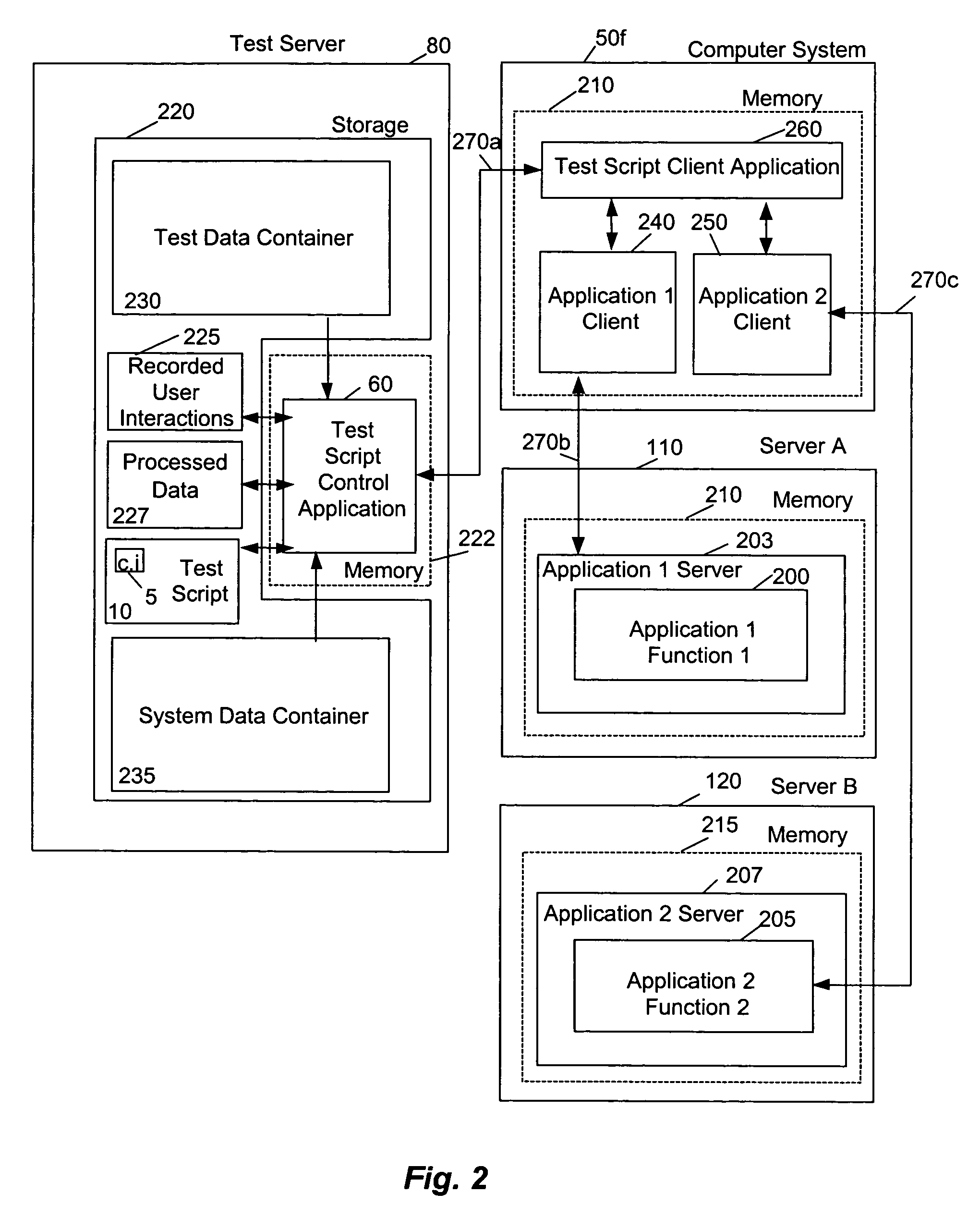
[0015]As shown in FIG. 1, a command interface 5 in accordance with the invention is included in a test script 10 resident on a test server 80 and may access test data 20 for testing applications 40a,b that are stored and executed on computers 50a–e. The command interface 5 may also be used to test an application that has a client part 41a executing on computer 50f and / or a server part 41b executing on server B 110, as well as an application that has a client part 42a executing on computer 5...


PUM


Abstract

A system and method for testing an application on a target system are described. The target system is assigned a logical name which is used by within a test script to reference the target system. The logical name is associated with a plurality of different communication channels within a system data container (e.g., remote function call (“RFC”) channels, HyperText Transport Protocol (“HTTP”) channels, . . . etc). During replay of the test script, a particular communication channel is selected from the plurality of communication channels based on the type of command within the test script that references the target system using the logical name.

Description

BACKGROUND[0001]1. Field of the Invention[0002]This invention relates generally to the field of data processing systems. More particularly, the invention relates to a system and method for identifying a system under test.[0003]2. Description of the Related Art[0004]To ensure proper operation, software applications are generally tested before they are deployed, for example, within a network. In one approach to testing, known inputs are supplied to one instance of the application during execution to establish what the predicted proper outputs should be. The inputs and predicted outputs are stored within a test script. The test script may then be played back to test another instance of the application. For example, the same inputs may be applied to the other instance of the application and the resulting outputs may then be compared against the predicted outputs to determine whether the other instance of the application is functioning properly.[0005]When features of an application are c...

Claims


Application Information

Patent Timeline
Patent Type & Authority Patents(United States)
IPC IPC(8): G06F9/44G06F11/00
CPCG06F11/006
Inventor BISCHOF, JOERGMUELLER, HORSTFICHTNER, JENS
Owner SAP AG
Learn More