
Seabed seismic station packaging

a seismic station and packaging technology, applied in the field of ocean bottom seismic surveying, can solve the problems of undesirable cross sensitivity, unfavorable letting pressure variations influence the geophone, etc., and achieve the effect of stabilizing the internal pressur

Active Publication Date: 2009-06-23
OPTOPLAN
View PDF24 Cites 32 Cited by
  • Summary
  • Abstract
  • Description
  • Claims
  • Application Information

AI Technical Summary

Benefits of technology

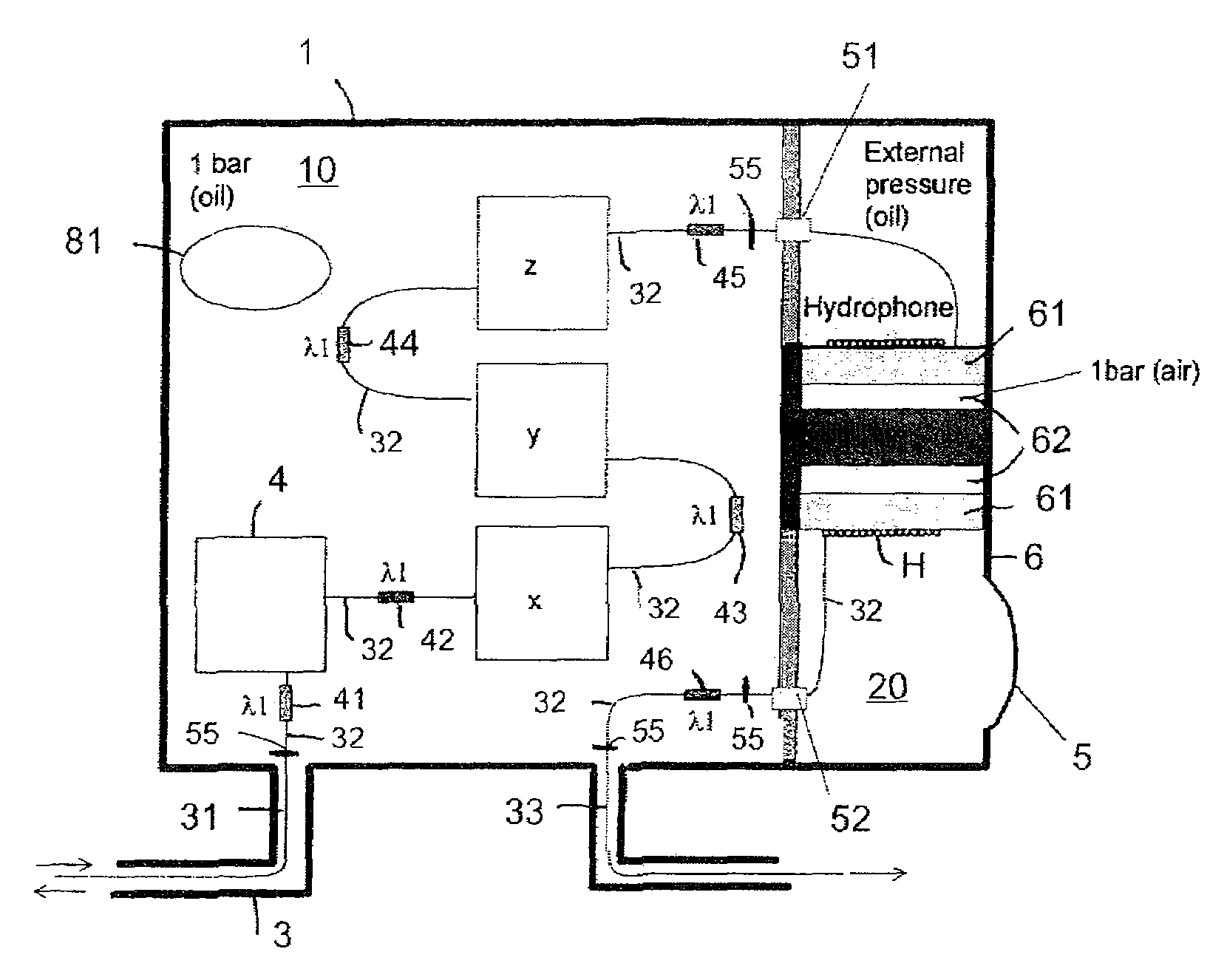
"The invention is about a seismic sensor station that includes a fiber optic hydrophone and a fiber optic accelerometer. The accelerometer is placed in a liquid filled compartment to dampen mechanical resonances caused by pressure fluctuations. The fiber optic hydrophone and accelerometer are connected by optical fiber. The housing has an array of fiber Bragg gratings forming interferometers for each sensor and a reference. A pressure transfer device is used to transfer pressure variations between the surrounding environment and the inside of the housing. The pressure balanced housing includes a flexible membrane or liquid filled bladder for pressure compensation. The accelerometer and hydrophone can be placed in the same liquid filled compartment or separate compartments. An internal bladder can also be used for pressure compensation and air-backing of the hydrophone. A high pressure accumulator is used for accommodating changes in temperature or pressure inside the housing."

Problems solved by technology

A general problem of arranging a hydrophone together with a three-axis geophone or accelerometer in a four-component seismic sensing station is the cross sensitivity between the hydrophone and the geophones / accelerometers.
While it is generally desirable to optimize the exposure of the hydrophone to pressure variations, it is generally undesirable to let pressure variations influence the geophones.
The influence of the pressure signal on the geophones / accelerometers creates an undesirable cross sensitivity.
Other potential problems exist with arrangements in the four-component seismic sensing station.
One problem of mounting geophones / accelerometers inside an air-filled pressure sealed housing involves mechanical resonances in the geophones / accelerometers.
Integrating several fiber optic sensors along a fiber loop in subsea environments creates other limitations relating to connecting arrangements, which require high pressure penetrators for guiding a fiber between low pressure surroundings and high pressure surroundings, and vice versa.

Method used


Image

  • Seabed seismic station packaging
  • Seabed seismic station packaging
  • Seabed seismic station packaging

Examples


second embodiment

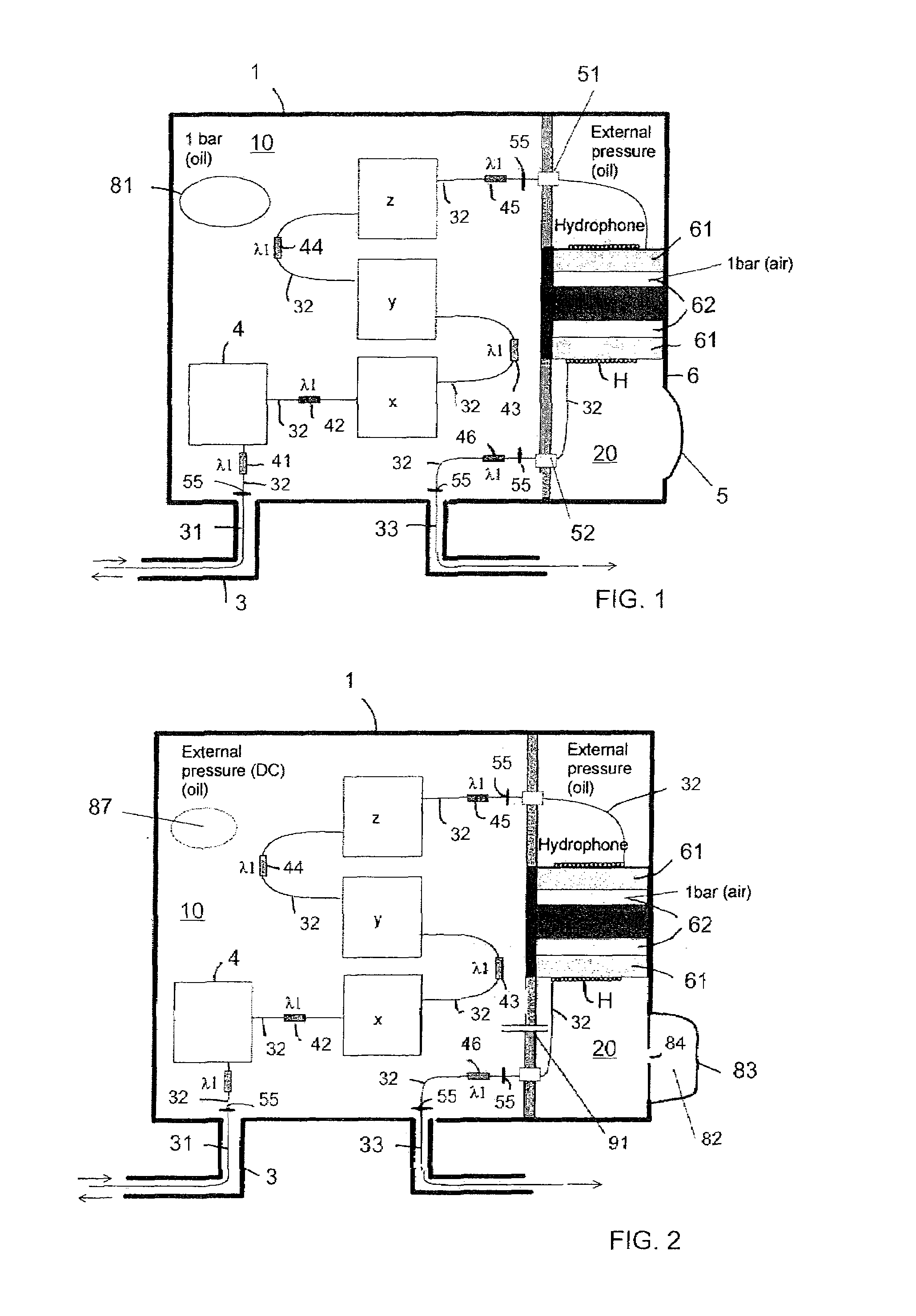
[0037]FIG. 2 illustrates the seismic sensor housing 1 according to the invention in which the optical fiber 31, 32, 33 is arranged in the same manner as in FIG. 1. However, the pressure regime of the housing 1 is different. In FIG. 2, there is shown a thin tube 91 between the first compartment 10 and the second compartment 20 of the housing 1. The effect of the thin tube 91 is to effectively balance, at slow pressure variations, the internal pressure of the first compartment 10 to the pressure of the second compartment 20 and the external pressure via an oil filled bladder 82 and the thin tube 91. The thinness of the tube 91 effectively creates a delay in the pressure balancing function, whereby slow pressure variations are balanced out as the tube has time to pass enough liquid to equalize the pressures of the first and second compartments, while fast pressure fluctuations cannot be equalized due to the delay caused by the thinness of the tube. The thinness of the tube 91 can be ch...

third embodiment

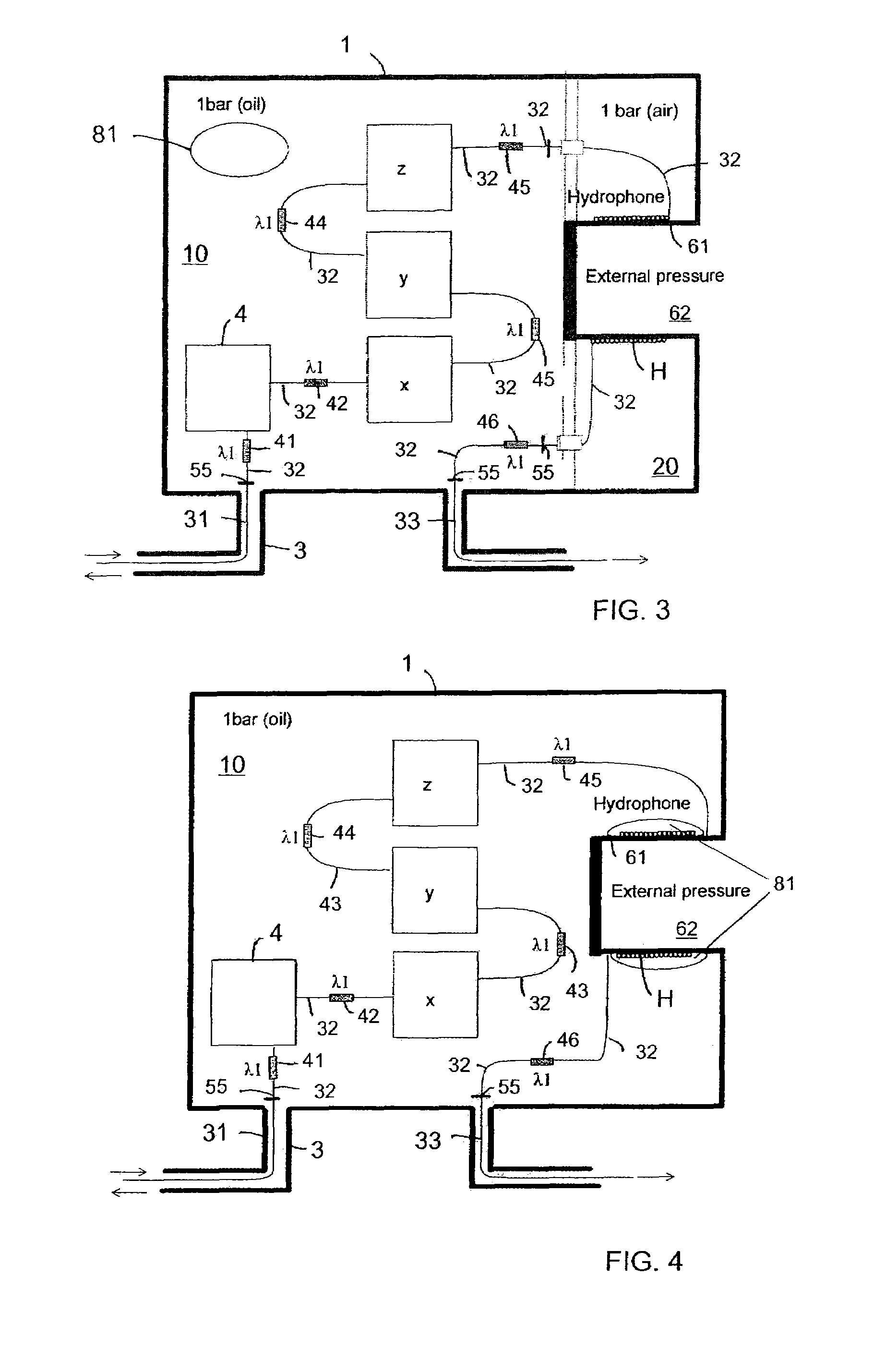
[0043]FIG. 3 shows the seismic sensor housing 1 according to the invention in which the optical fiber 31, 32, 33 is arranged in the same manner as in FIG. 1, but the pressure regime of the hydrophone is different from the one in FIG. 1. In FIG. 3, the internal volume 62 defined by the structure 61 is open towards the external environment. Beneficially, the second compartment 20 of the housing which accommodates the optical fiber coil of the hydrophone H is then a part of the pressure sealed part of the housing 1, whereby internal high pressure penetrators are avoided. Further, the mounting of the optical fiber coil of the hydrophone H is simplified, so that the fiber can be fairly loosely arranged prior to deployment, while the increasing external pressure during deployment causes a tightening of the fiber coil when subject to the pressures at large sea depths. The second compartment 20 accommodating the hydrophone coil can be air filled, effectively creating an air backed hydrophon...


PUM


Abstract

A seismic sensor station includes a housing containing a fiber optic hydrophone and a fiber optic accelerometer that can both be made from a single length of optical fiber arranged inside the housing. The fiber optic accelerometer is arranged in a liquid / oil filled compartment of the housing for dampening of mechanical resonances in the accelerometer due to mechanical disturbances and pressure fluctuations.

Description

BACKGROUND OF THE INVENTION[0001]1. Field of the Invention[0002]Embodiments of the invention relate to ocean bottom seismic surveying using seismic sensors deployed at the bottom of the sea. More particularly, embodiments of the invention relate to a seismic station housing in an ocean bottom seismic surveying system using an ocean bottom deployed seismic cable with seismic stations along its length.[0003]2. Background and Prior Art[0004]Seismic surveying using fiber optic technology has recently received attention. Optical based sensors for performing the surveying can include a hydrophone and geophones. These sensors can be fabricated, for example, using Michelson interferometers.[0005]A general problem of arranging a hydrophone together with a three-axis geophone or accelerometer in a four-component seismic sensing station is the cross sensitivity between the hydrophone and the geophones / accelerometers. While it is generally desirable to optimize the exposure of the hydrophone to...

Claims


Application Information

Patent Timeline
Patent Type & Authority Patents(United States)
IPC IPC(8): G01V8/24G01H9/00G01V1/38G01V8/16
CPCG01V1/16G01V1/38G01V8/16G01V8/24
Inventor BERG, ARNERONNEKLEIV, ERLENDWAAGAARD, OLE HENRIKKRINGLEBOTN, JON THOMASNAKSTAD, HILDEFURUHAUG, ROAR
Owner OPTOPLAN
Learn More