
Hinged derail with assisted manual lifting and method for constructing

a technology of assisted manual lifting and guiding derailment, which is applied in the direction of railway auxiliaries, transportation and packaging, and interlocking of points, etc., can solve the problems of physical injury, heavy derail shoes are not easily manually rotated between operative and inoperative positions, and the derail shoes are made of solid steel. , to achieve the effect of reducing stress on the worker, no weight, and light weigh

Active Publication Date: 2009-06-23
WESTERN CULLEN HAYES
View PDF15 Cites 7 Cited by
  • Summary
  • Abstract
  • Description
  • Claims
  • Application Information

AI Technical Summary

Benefits of technology

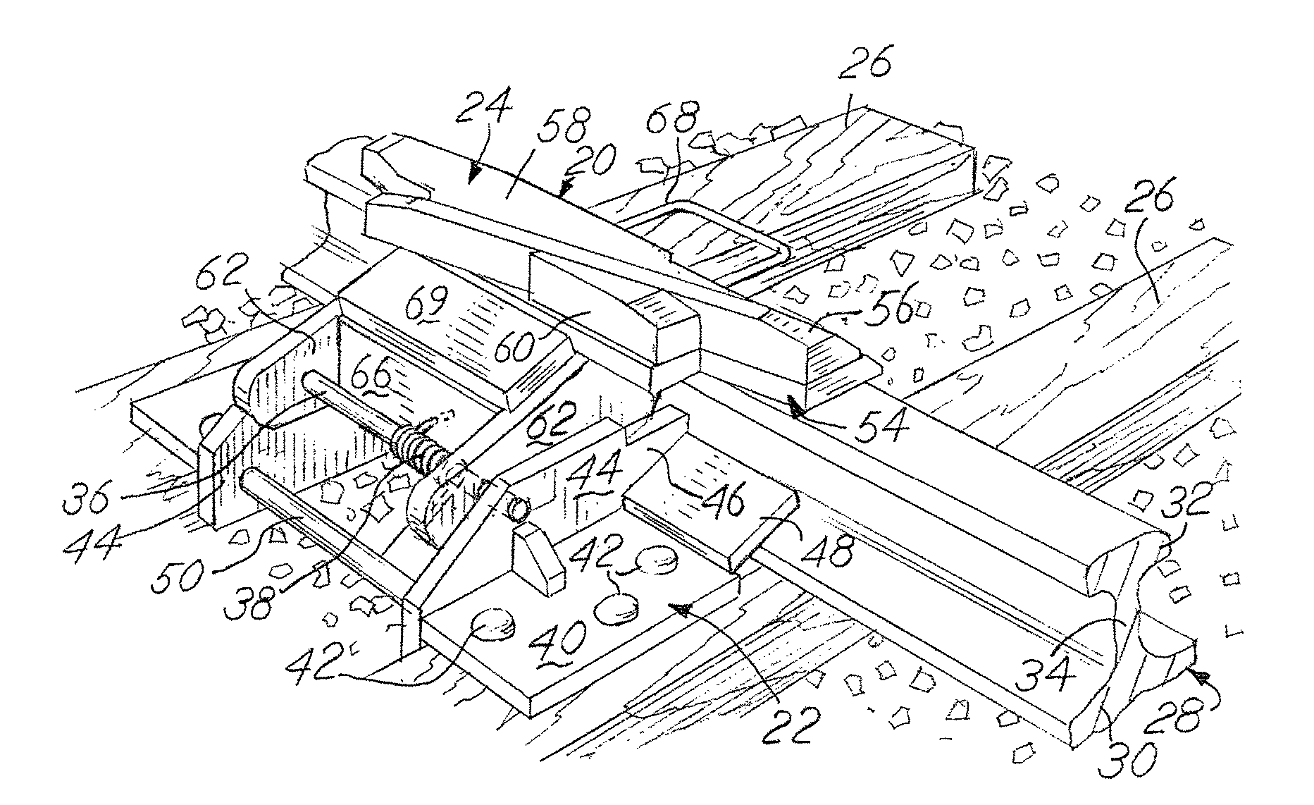
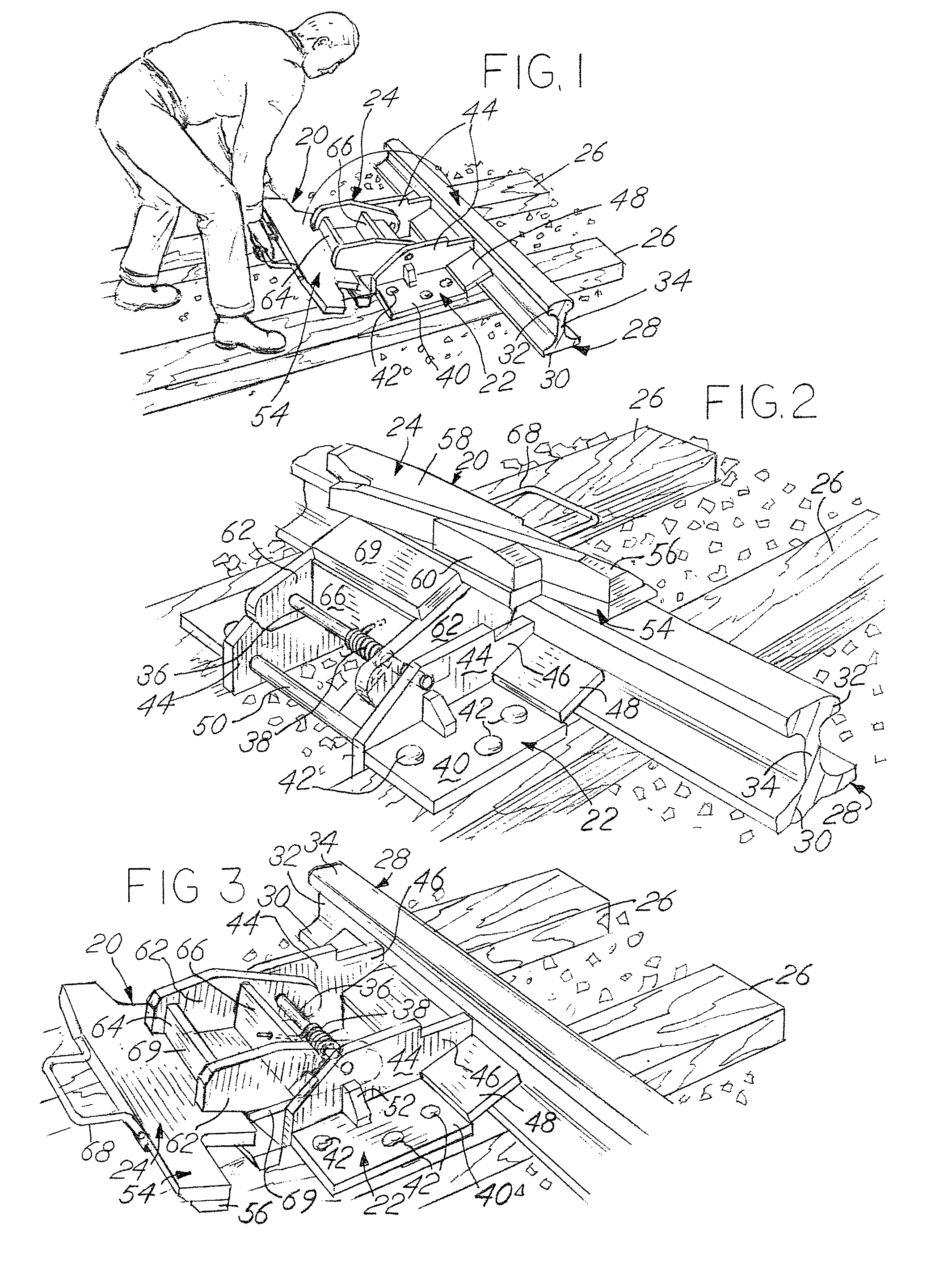
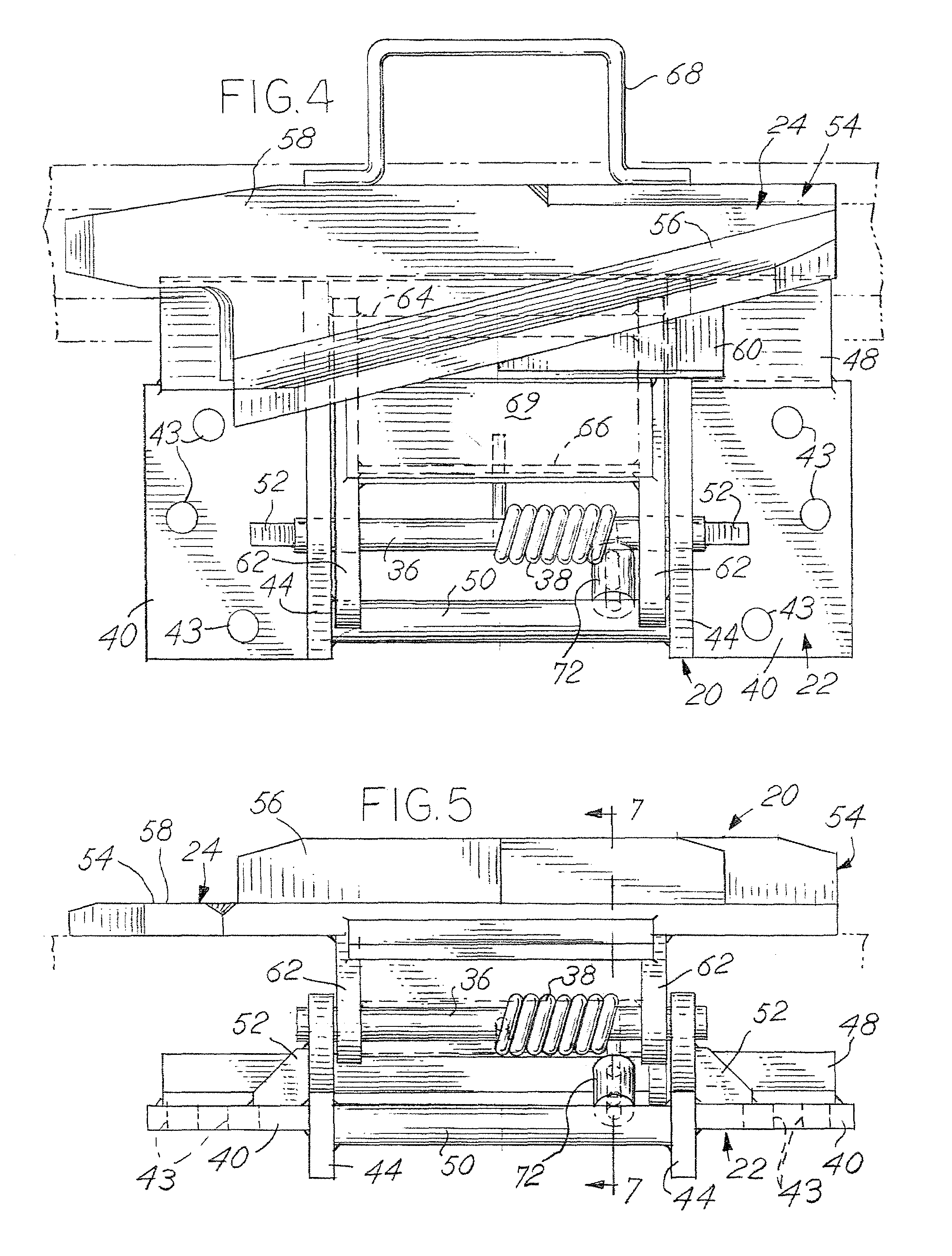
[0008]The above mentioned need for assistance in manually moving the derail shoe both from the inoperative position to the operative position and from the operative position to the inoperative position is accomplished by providing a biasing member on both the derail base and the derail shoe wherein the biasing member provides lifting assistance to the manual lifting of the shoe when the shoe is in both the operative position and the inoperative position. Preferably, a torsion spring is physically positioned around a pivot shaft which is mounted on the derail base and on the derail shoe and which provides a pivot axis for the derail shoe. One end of the torsion spring is secured to the base and the other end of the torsion spring is affixed to the derail shoe. More preferably, the design of the torsion spring is such that it provides lifting force for assistance to the worker to relieve stress on the worker when the derail shoe is lifted and rotated. This is accomplished by designing the torsion spring to be in a stressed condition, that is, in a wound condition or in an unwound condition, when the derail shoe is in the full operative position or in the full inoperative position. In one embodiment, where the derail shoe is relatively light in weight, the torsion spring is in a stressed, unwound condition when the derail shoe is in inoperative, on the rail and is in a stressed, wound condition when the derail shoe is the inoperative, off-rail position. Similarly, another embodiment, when the derail shoe is relatively heavy in weight, such as in the case of a double ended derail, the torsion spring is also in a stressed, unwound condition when the derail shoe is in the inoperative, off rail position and is in a stressed, wound condition when the derail shoe is in the operative, on rail position. The spring is designed to be in a substantially relaxed position when in a generally upright position. The operator thereby has the benefit of the lifting force of the torsion spring both when the spring is in the stressed, wound position and in the stressed, unwound position with the spring being substantially relaxed or unstressed in the upright position. The use of the torsion spring adds no weight to the pivoted derail shoe, requires no external assistance such as from a powerized source, and is of economical design. The method for manufacturing the hinged derail with the torsion spring involves installing the spring when the shoe is generally upright relative to the base and when the spring is relaxed to thereby enable the spring to provide the desired lifting force for assisting the worker when the derail is in both the operative position and in the inoperative position.

Problems solved by technology

The derails are made of solid steel and are very heavy as they must derail a heavy, moving rail car.
Clearly, any of the heavy derail shoes are not easily manually rotated between operative and inoperative positions.
This action is physically difficult and can cause physical injury, such as to the back of the railroad worker.
Similarly, when the derail shoe with the deflecting block is moved by the worker in the opposite direction, that is, from the deflecting or operative position to the inoperative position, the same problem occurs, that is the heavy derail shoe must be lifted and rotated in the opposite direction to the inoperative position.
Again, the operator risks or may even encounter serious injury such as to the back.

Method used


Image

  • Hinged derail with assisted manual lifting and method for constructing
  • Hinged derail with assisted manual lifting and method for constructing
  • Hinged derail with assisted manual lifting and method for constructing

Examples


second embodiment

[0038]the invention is shown in FIGS. 9-11. A double ended derail assembly, generally 200, is shown. The derail assembly 200 includes a derail base, generally 202 which pivotally carries a derail shoe, generally 204. The derail assembly 200 is shown in the operative position on a rail 28, shown in dotted line view in FIGS. 9 and 11. Also shown in dotted line view is a pair of railroad ties 26 mounted in a conventional manner transverse to the rail 28. The rail 28 rests upon the upper surface of the ties. The derail shoe 204 of the derail assembly 200 is pivotally mounted about a pivot shaft 206 which is spaced laterally inwardly from the rail 28 and is rigidly mounted on the derail base 202, to be described hereinafter in greater detail.

[0039]A torsion spring, generally 208, as seen in solid-line view in FIGS. 9 and 10 and in dotted-line view in FIG. 11 provides upward biasing or lifting assistance to the operator when the operator manually lifts the derail shoe 204 whether the dera...

embodiment 200

[0048]The specifications for the spring 208, as would be apparent to one skilled in the art, vary depending on the weight of the derail shoe 204. In the double ended derail embodiment 200 of FIGS. 9-11, for example, when the weight of the shoe is heavier in weight and may weigh about 110-120 pounds, the specifications of the spring 208 are as follow:

[0049]

TorsionCylindClose Wound Chrome VanadiumRoundWire Dia (in)0.4060Mean Dia (in)1.7300 + .032Active Coils13.2300Rate (#-in / deg)9.1600Inside Dia (in)1.3240Total Coils13.2300Spring Index C4.2611Outside Dia (in)2.1360Active Legs (in)0.0000Nat Preg (Hz)82.3814Min I.D. (in)1.2867Addl Feed (in)0.0000Body Length (in)5.7774Devel Lngth (in)71.9045Max Bdy Len (in)5.8958Weight (lbs)2.6437FreePoint 1Point 2Moment Arms (in)Force at Arm (lbs)Moment (#-in)Angle (deg)262.8000Deflection (deg)UNK Stress (psi)UNK Stress % of MTS

Manufacturing Method for the Embodiment of FIGS. 9-11

[0050]It is to be understood that the method of manufacturing the double e...


PUM


Abstract

This invention relates to hinged derail assemblies used in the railroad industry for derailing a wheel of an undesirably moving railed vehicle. The hinged derail assembly includes a base that is positioned adjacent one rail of a pair of railroad rails. A derail shoe is pivotally mounted on the derail base and is moveable between a derailing position and an inoperative position. In the present invention a biasing member, such as a torsion spring, is secured to both the base of the hinged derail assembly and the derail shoe. The spring provides upward lifting force whether the derail shoe is in the inoperative position or in the derailing position. This lifting force assists the worker in the manual lifting of the derail shoe. The invention also relates to a method of constructing the hinged derail wherein the torsion spring is installed when the derail shoe is generally upright.

Description

REFERENCE TO RELATED APPLICATION[0001]This application is a continuation-in-part application of U.S. application Ser. No. 11 / 493,115 filed on Jul. 26, 2006.BACKGROUND OF THE INVENTION[0002]This invention relates generally to safety equipment, namely, derails, which are commonly used for derailing railed vehicles, particularly powered and non-powered railroad cars such as box cars, flat bed railroad cars and the like, which are undesirably moving along railroad tracks. More specifically, the invention relates to hinged derails which may be selectively positioned adjacent one of a pair of railroad tracks for movement between an operating position for engaging and derailing a wheel of an undesirably moving railroad car and an inoperative position for allowing a moving railroad car to pass by the derail without undesirably engaging and derailing the moving railroad car. This invention also relates to a method for constructing the hinged derail of the invention.[0003]Derails of various t...

Claims


Application Information

Patent Timeline
Patent Type & Authority Patents(United States)
IPC IPC(8): B61L19/02B61K5/00
CPCB61K5/06
Inventor HERTEL, KEVIN
Owner WESTERN CULLEN HAYES
Learn More