Signal amplification through an electromagnetic device

a technology of electromagnetic devices and signals, applied in the direction of amplifiers with tubes, electric generator control, dynamo-electric converter control, etc., can solve the problems of significant increase in manufacturing costs and inherent noise, and increase the signal-to-noise ratio of circuits

Inactive Publication Date: 2009-06-09
RODRIGUEZ MANUEL DE JESUS
View PDF19 Cites 14 Cited by
  • Summary
  • Abstract
  • Description
  • Claims
  • Application Information

AI Technical Summary

Benefits of technology

[0045]the signal comparator circuit is comprised of a comparator amplifier with an output coupled with a low-pass filter comprised of a resistor and a capacitor combination, which loop and feedback the system input signal to a negative input of the signal comparator circuit for controlling a bandwidth of the main output signal, and facilitating a control for a phase gain of system input signal.
[0053]the polarity detector is comprised of an amplifier that functions as a linear signal amplifier with a controlled gain for a first input level signal for reducing possible cross-over distortions, and functions as a switching amplifier for a second input level signal.
[0072]a protection circuit having one end coupled with a second end of the first switching system, and another end coupled with the variable impedance circuit, with the protection circuit providing sufficient impedance to prevent the flow of the main input signal back to the voltage references when the second switching system is actuated for disabling supply of the main input signal.
[0087]a protection circuit having one end coupled with the Alternative Current voltage source, and another end coupled with the variable impedance circuit, with the protection circuit providing sufficient impedance to prevent the flow of the main input signal back to the AC voltage reference when the switching system is actuated for disabling supply of the main input signal.

Problems solved by technology

A typical class AB amplifier includes a power supply and an amplifier, both of which significantly increase manufacturing costs.
Other conventional amplifiers such as the class D amplifiers always switch at fifty percent duty cycle even without application of any signal, which causes an inherent noise that increases the signal-to-noise ratio of a circuit.

Method used


Image

  • Signal amplification through an electromagnetic device
  • Signal amplification through an electromagnetic device
  • Signal amplification through an electromagnetic device

Examples


Embodiment Construction

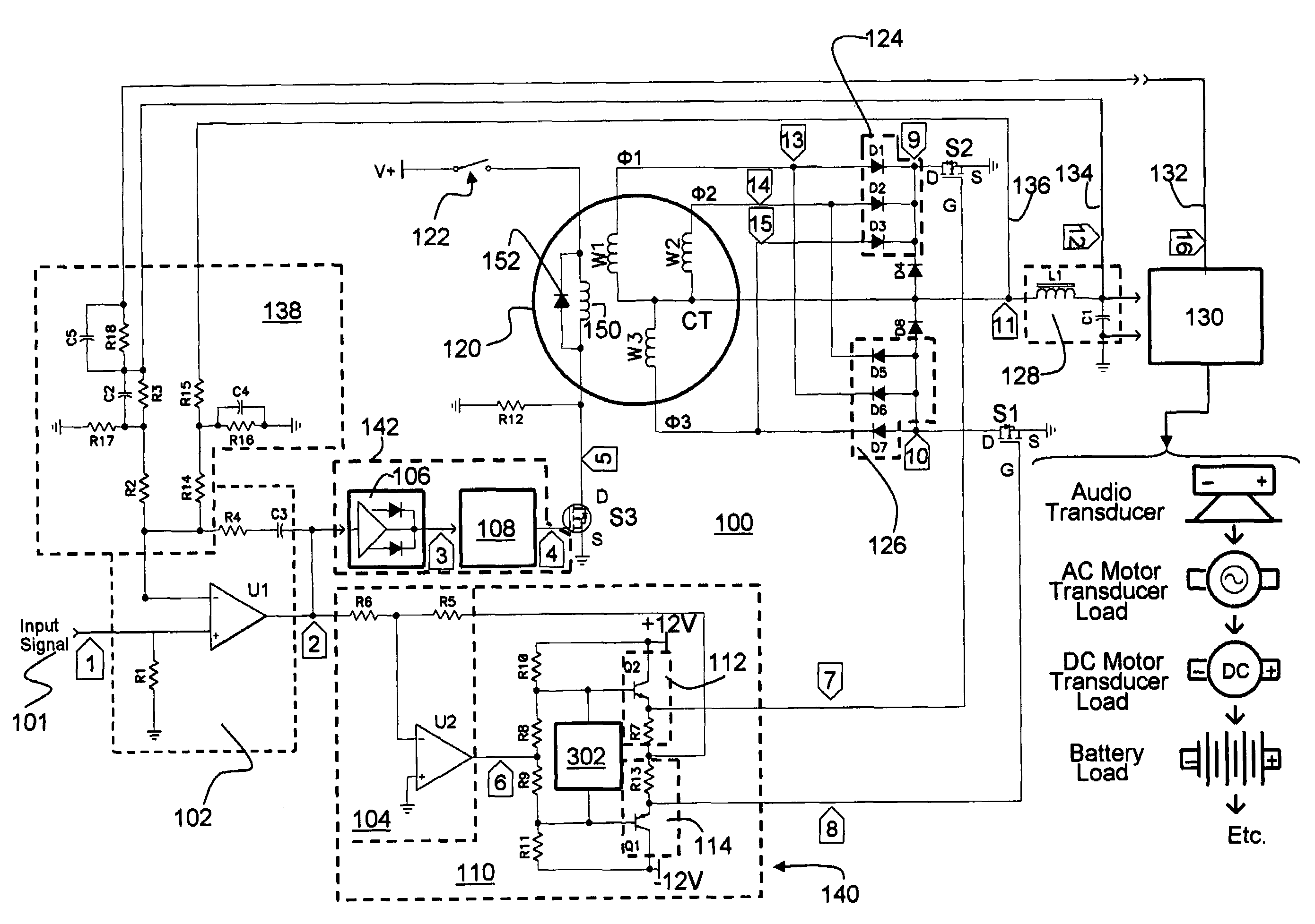
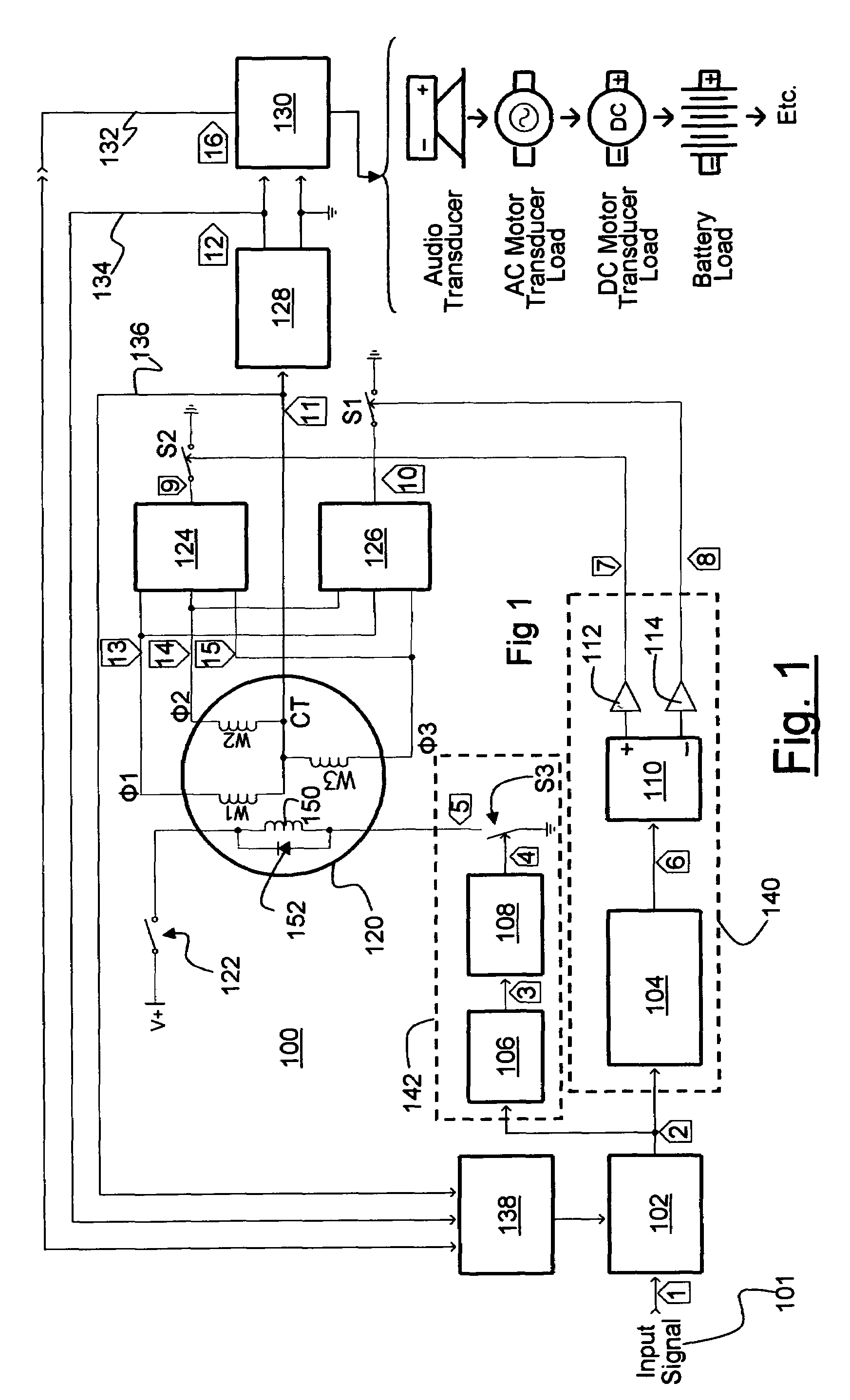
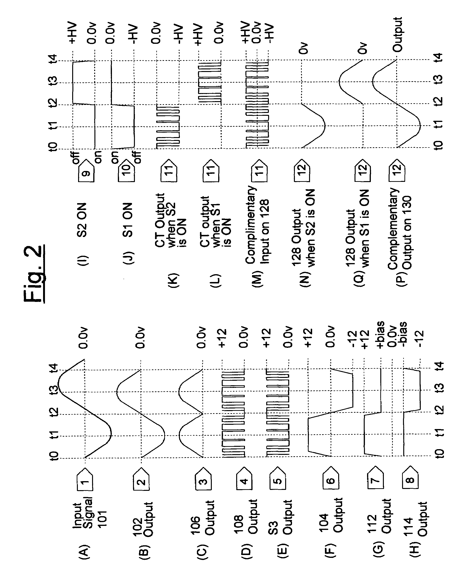
[0115]FIG. 1 is an exemplary block diagram illustration of a signal amplifying system 100 in accordance with the present invention, and FIGS. 2(A) to 2(P) are waveform diagrams illustrating the various waveforms at particular points in the circuit of FIG. 1. The signal amplifying system 100 of the present invention uses an electromagnetic device 120 for amplifying an input signal 101 for deriving a load 130, thereby avoiding the use of amplifiers, power supplies, and inverter / converter circuits. A non-limiting example of an electromagnetic device 120 that may be used within the signal amplifying system 100 of the present invention may include a conventional alternator. Alternators are well-known devices that convert mechanical energy into electrical energy.

[0116]As illustrated in FIG. 1, a main input signal 101 indicated at point 1 and illustrated in FIG. 2(A) is coupled with the circuit 100 to derive a load 130 via a signal comparator circuit 102, with an output signal that is defi...


PUM


Abstract

The present invention uses an electromagnetic device for amplifying an input signal without the use of amplifiers, power supplies, and inverter / converter circuits. The present invention routes an input signal through an electromagnetic device for amplification of the input signal for later use by various loads.

Description

BACKGROUND OF THE INVENTION[0001](1) Field of the Invention[0002]This invention relates to signal processing through an electromagnetic device and, in particular, to system and method for signal amplification via the electromagnetic device without the use of power amplifiers, separate power supplies, and power inverters.[0003](2) Description of Related Art[0004]Amplifying circuits are well known in the prior art and generally require a power amplifying stage. Such power amplifier circuits are illustrated in U.S. Pat. Nos. 4,409,559 and 4,651,112.[0005]A typical class AB amplifier includes a power supply and an amplifier, both of which significantly increase manufacturing costs. Prior art circuits that avoid the requirement of a power amplifier are disclosed in the U.S. Pat. Nos. 4,763,080; 4,517,522; 4,047,120; and 4,453,131. Other conventional amplifiers such as the class D amplifiers always switch at fifty percent duty cycle even without application of any signal, which causes an ...

Claims


Application Information

Patent Timeline
Patent Type & Authority Patents(United States)
IPC IPC(8): H03F9/00
CPCH03F1/02H03F3/217H03F3/45475H03F21/00H03F2200/537H03F2203/45138H03F99/00
Inventor RODRIGUEZ, MANUEL DE JESUS
Owner RODRIGUEZ MANUEL DE JESUS
Why Eureka
Try Eureka