
Adjustable corpectomy apparatus

Active Publication Date: 2009-06-09
THEKEN SPINE
View PDF508 Cites 133 Cited by
  • Summary
  • Abstract
  • Description
  • Claims
  • Application Information

AI Technical Summary

Benefits of technology

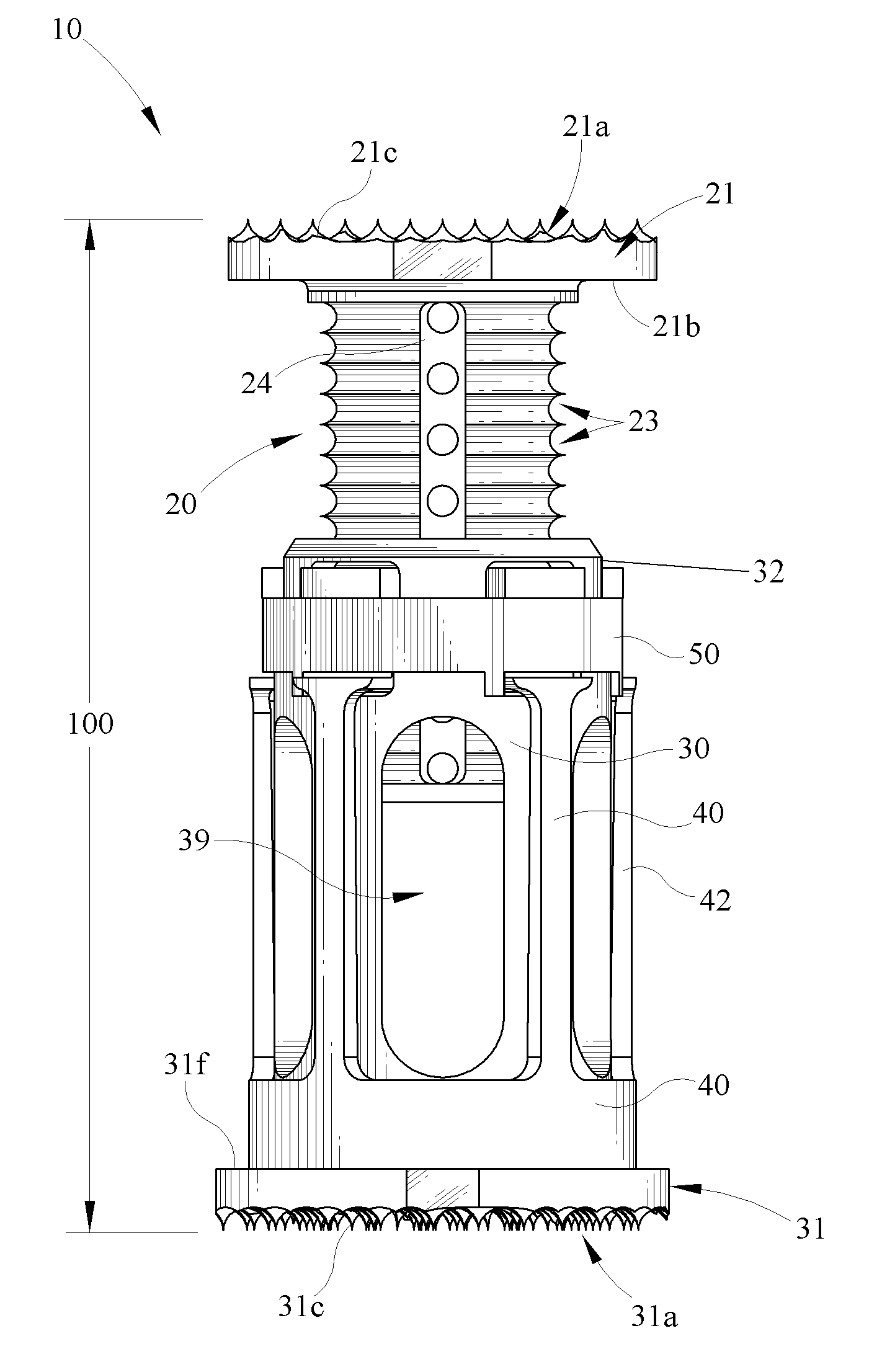
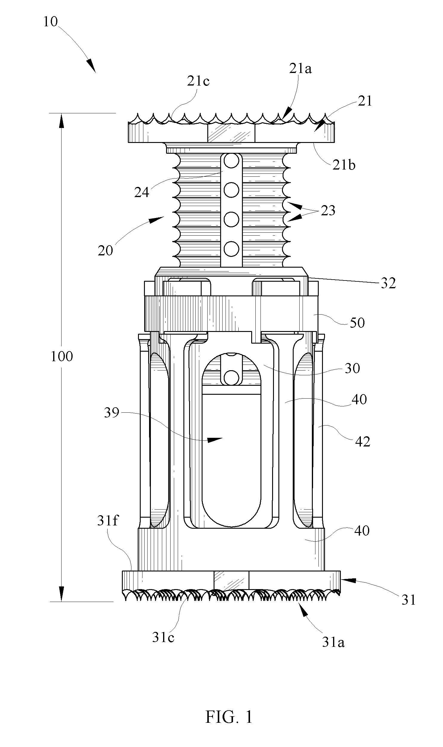
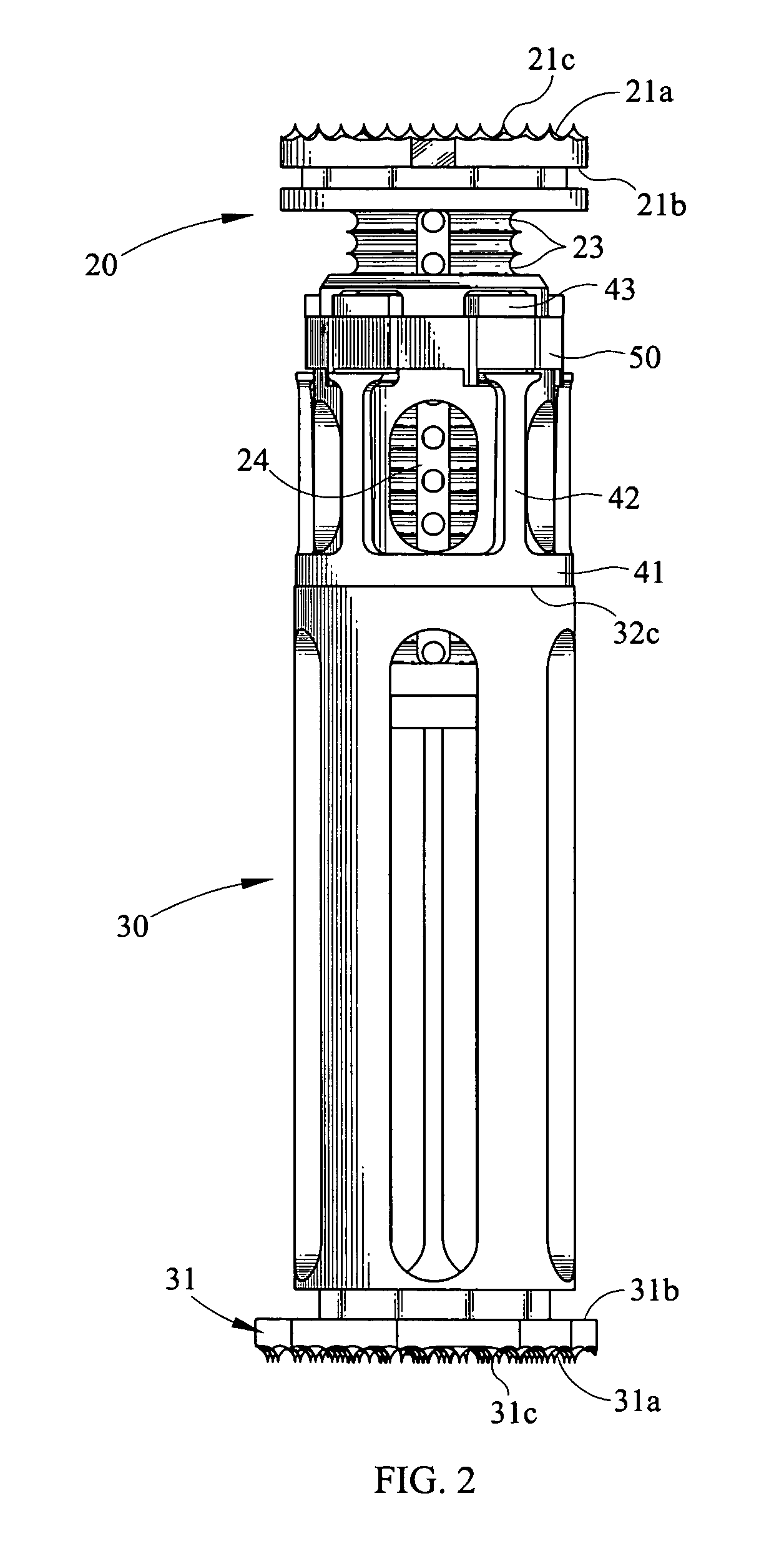
[0013]The first surfaces of each endplate interact with the healthy bone adjacent each end of the prosthesis. One or both endplates may include a feature located on its first surface that encourages and / or facilitates fusion of the prosthesis and the healthy bone. This feature can be in the form of physical protuberances (such as spikes, ridges, keels, knurling, and the like) or chemical or biological treatments such as hydroxyapatite and the like. This improves the fixation characteristics of the prosthesis and lengthens the overall life of the prosthesis. The footprint and angle of the first surface of both the first and second endplates can be varied depending on the location of placement in the spine.
[0017]A locking mechanism comprises a ring that fits around the fingers of the finger cage. The locking mechanism preferably has two positions—locked and unlocked. When in the locked position, the tabs of the fingers are forced through the locking apertures of the finger cage and mesh with the grooves of the inner member. Which grooves of the inner member the tabs of the fingers engage depends upon how far the inner sleeve is inserted into the outer sleeve. Therefore, when the locking mechanism is in the locked position, the inner member is prevented from sliding axially with respect to the outer member, and the height of the apparatus is thus fixed.

Problems solved by technology

This improves the fixation characteristics of the prosthesis and lengthens the overall life of the prosthesis.

Method used


Image

  • Adjustable corpectomy apparatus
  • Adjustable corpectomy apparatus
  • Adjustable corpectomy apparatus

Examples


Embodiment Construction

[0030]While the present invention will be described more fully hereinafter with reference to the accompanying drawings in which particular embodiments and methods are shown, it is to be understood from the outset that persons of ordinary skill in the art may modify the invention herein described while achieving the functions and results of this invention. Accordingly, the description that follows is to be understood as illustrative and exemplary of specific embodiments within the broad scope of the present invention and not as limiting the scope of the invention. In the following descriptions, like numbers refer to similar features or like elements throughout.

[0031]Ideally, an artificial corpectomy prosthetic provides the surgeon with an easy adjustment mechanism that allows the length of the prosthetic to be modified during surgery with a minimum of time and effort to fit the needs of the patient. The prosthetic must allow a significant range of adjustment because the size and numb...


PUM


Abstract

A spinal fixation apparatus comprising an upper and lower endplate. Depending distally in a longitudinal direction from the upper endplate is an inner sleeve that fits inside an outer sleeve that depends distally in a longitudinal direction from the lower endplate. The inner sleeve includes grooves located on its outer surface. A finger cage including resilient fingers fits around the outer sleeve. The fingers have ends that include male grooves. The ends of the fingers fit into apertures located in the outer sleeve. The apparatus further includes a locking mechanism that pushes the tips of the fingers through the apertures of the outer sleeve such that they mesh with the grooves of the inner sleeve. When the locking mechanism is unlocked the tips of the fingers disengage from the grooves of the inner sleeve, and the inner sleeve slide axially within the outer cage, adjusting the height of the device.

Description

CROSS REFERENCE TO RELATED APPLICATIONS[0001]This application claims the benefit of U.S. Provisional Application Nos. 60 / 567,619 filed May 3, 2004; 60 / 567,618 filed May 3, 2004; 60,567,667 filed May 3, 2004; 60 / 567,554 filed May 3, 2004; 60 / 567,555 filed May 3, 2004; 60 / 567,556 filed May 3, 2004; 60 / 567,564 filed May 3, 2004; the entire disclosures of which are incorporated herein by reference.BACKGROUND OF THE INVENTION[0002]1. Field of the Invention[0003]The present invention generally relates to the field of orthopaedic implants. Specifically, the present invention provides a prosthetic implant to replace spinal vertebra and adjacent intervertebral discs.[0004]2. Background[0005]The vertebral column serves as the main structural support of the human skeleton. The vertebral column consists of a number of vertebrae separated by intervertebral discs. A vertebra approximates a cylindrical shape, with wing-like projections and a bony arch. The arches create a passageway through which ...

Claims


Application Information

Patent Timeline
IPC IPC(8): A61F2/44
CPCA61F2/44A61F2002/30383A61F2002/30495A61F2002/30507A61F2002/3055A61F2002/30551A61F2002/30601A61F2002/30777A61F2002/30841A61F2002/4475A61F2220/0025A61F2310/00023A61F2002/30593
Inventor MUELLER, RICHARDBUDD, ANDREW
Owner THEKEN SPINE
Learn More