Link assembly for a snake like robot arm

a robot arm and link technology, applied in the direction of joints, programmed manipulators, automatic controllers, etc., can solve the problems of reducing the overall friction loss of the manipulator, and the difficulty of overcoming it, so as to reduce friction, reduce the difficulty of manufacturing in bulk, and facilitate the effect of reproducing large numbers

Inactive Publication Date: 2009-06-09
OLIVER CRISPIN ROBOTICS
View PDF15 Cites 29 Cited by
  • Summary
  • Abstract
  • Description
  • Claims
  • Application Information

AI Technical Summary

Benefits of technology

[0012]The elastomer may be of a natural or synthetic rubber or any other suitable resilient or elastomeric material. The elastomer is preferably disposed as a layer between said first and second link members. In one embodiment of the present invention, the first and second members may be configured in a co-operating mating relationship and the elastomer means may be disposed between them as a thin layer whereby a bending movement between the members produces shear movement within the elastomer means and reduces any compressive movement as a result of the relative movement between said first and said second members to a minimum. The elastomer may serve to produce axial stiffness and bending flexibility of the joint between the members.
[0032]By using apparatus in accordance with the present invention, it is possible to create paths by using a joystick control assembly for tip guidance, or in the alternative, off-line or on-line techniques can be provided for computer control through a CAD model of the proposed environment.

Problems solved by technology

In a multi-link segment, these friction losses build up and in a multiple segment robotic arm; the overall friction losses to be overcome during manipulation of the arm can be considerable.

Method used


Image

  • Link assembly for a snake like robot arm
  • Link assembly for a snake like robot arm
  • Link assembly for a snake like robot arm

Examples


Embodiment Construction

.

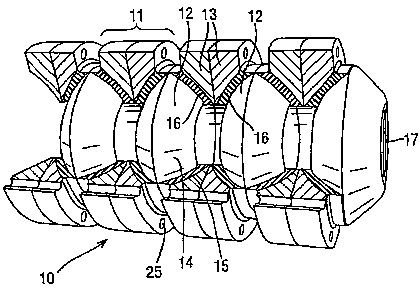
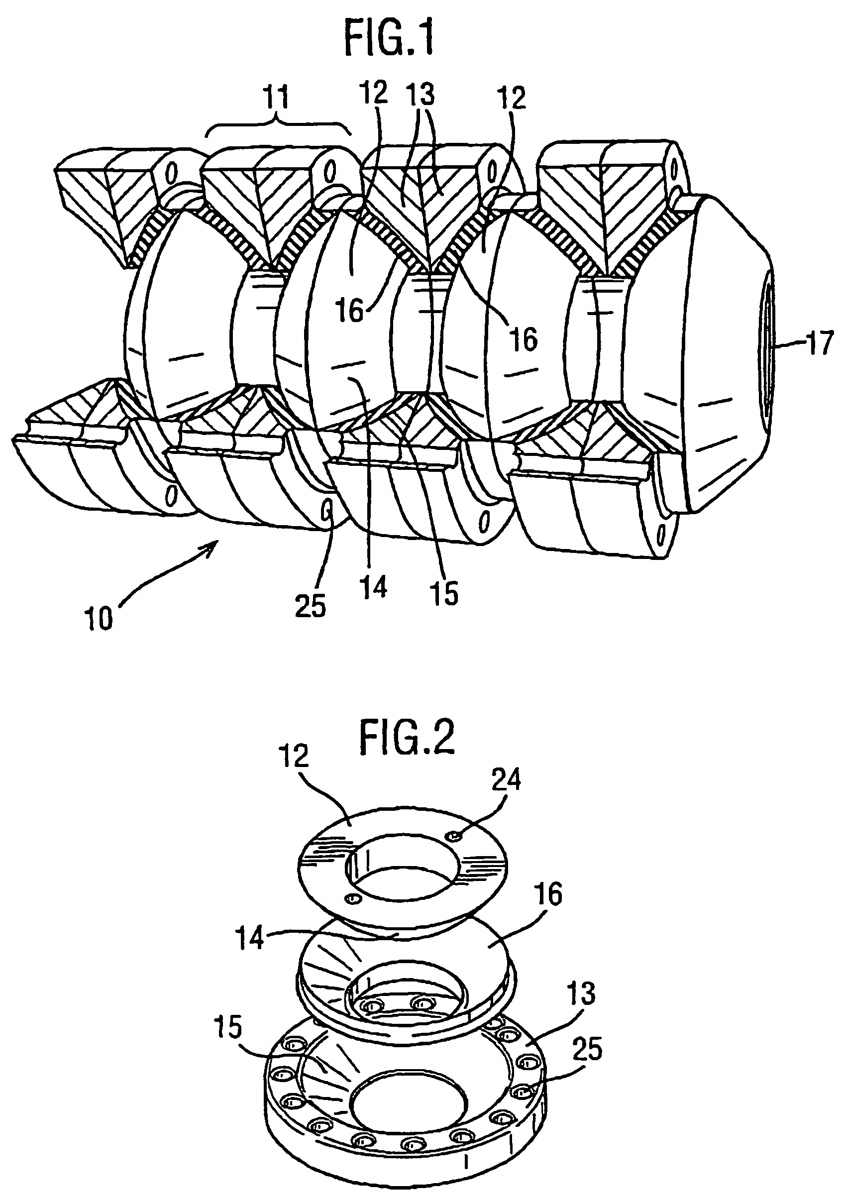
[0044]An arm in accordance with the present invention comprises a plurality of segments indicated generally at 10 arranged end-to-end to form an extended “snake” arm. Each segment comprises a plurality of link components indicated generally at 11. Each link component comprises an inner disc 12 and an outer disc and wire guide 13. The inner disc 12 is shaped to provide an arcuate annular surface indicated generally at 14 and the outer disc 13 has a matching arcuate surface 15.

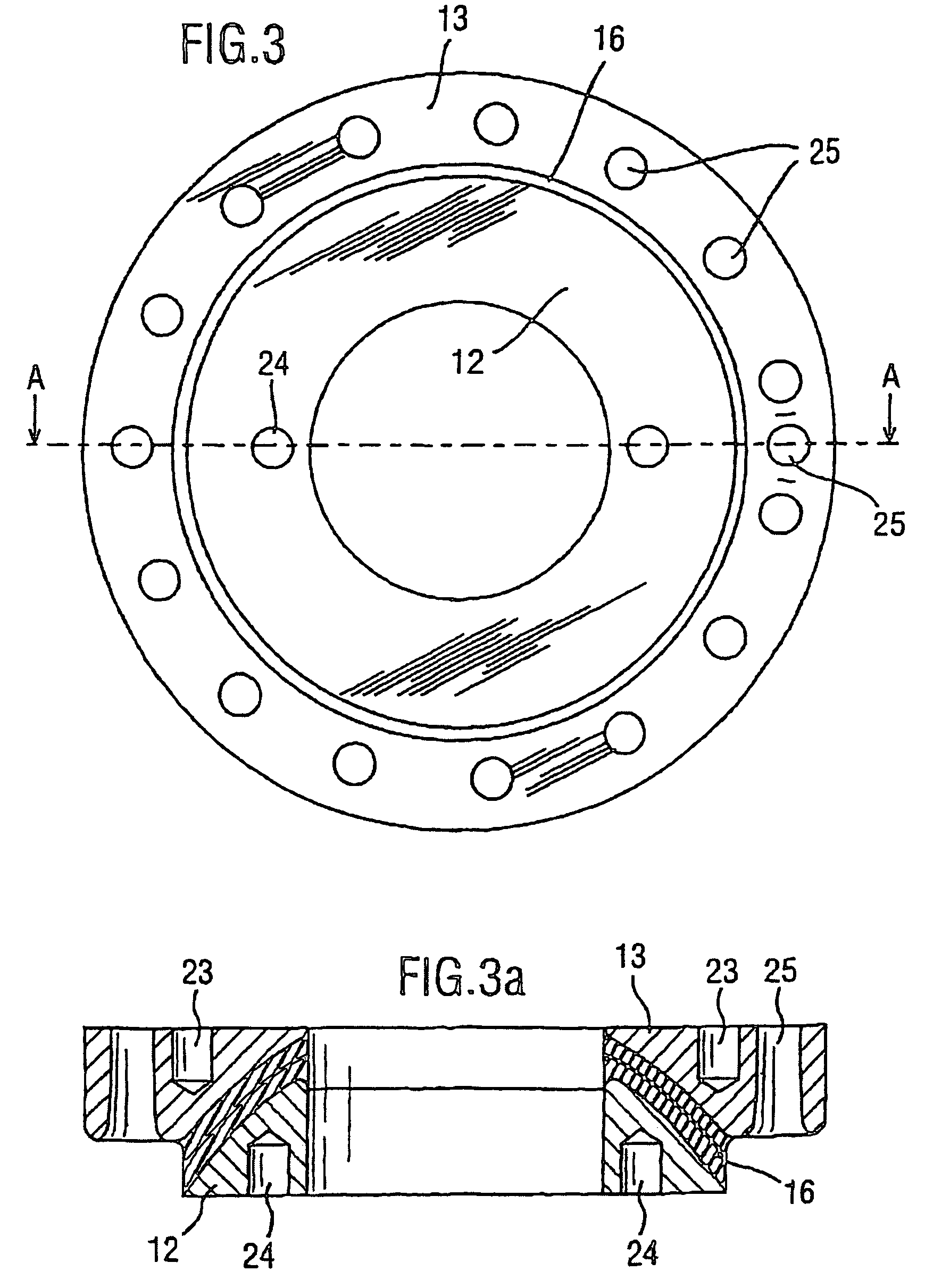
[0045]Assembled as shown in FIG. 1, the inner disc 12 and the outer disc 13 are separated by a layer of rubber 16 which may be formed in situ. Rubber layer 16 may be comprised of one or more layers of various types of elastomeric materials. Rubber layer 16 may also have disposed within it an interleaved rigid layer, formed of thin metal, resin, glass fiber, or the like, as seen in FIG. 3A. The rubber layer 16 is bonded to each of the outer disc 13 and the inner disc 12 to allow relative movement therebetween. E...


PUM


Abstract

The present invention relates to a link assembly for a robot arm which comprises first and second link members each adapted for limited movement one with respect to the other and resilient elastomeric material disposed between said first and second members and bonded or keyed thereto whereby movement between the first and second member results in shear movement within the elastomeric material disposed there between.

Description

[0001]This application is a continuation of pending International Patent Application No. PCT / GB02 / 02649 filed Jun. 12, 2002 which designates the United States and claims priority of pending British Application No. 0114406.2 filed Jun. 13, 2001.[0002]This invention relates to an improvement in the robotic positioning of work tools and sensors within a work environment, and has particular reference to improved mechanical and software tools for positioning a work tool or sensor.BACKGROUND OF THE INVENTION.[0003]Traditionally, mechanical equipment such as engines and machines incorporating a housing has been maintained by regular maintenance schedules. In the event of a malfunction, an operative or engineer will run the machine or engine through a series of test Functions in a trouble-shooting programme and take note of the reaction of the machine or engine to each test function from an observation of the action or reaction of the machine to a given test function, it is possible to diag...

Claims


Application Information

Patent Timeline
IPC IPC(8): B25J17/02B25J17/00B25J9/06B25J9/10B25J18/06
CPCB25J9/06B25J9/104B25J18/06Y10T74/20323Y10T74/20329
Inventor BUCKINGHAM, ROBERT OLIVERGRAHAM, ANDREW CRISPIN
Owner OLIVER CRISPIN ROBOTICS
Why Eureka
Try Eureka