
Multi-stage hinge assembly and electrical device

a multi-stage, hinge technology, applied in the direction of instruments, details of portable computers, casings/cabinets/drawers, etc., can solve the problems of damage to the side frame of the liquid crystal display b>11/b>, increase the frictional force, and reduce the for

Active Publication Date: 2009-06-09
ASUSTEK COMPUTER INC
View PDF18 Cites 15 Cited by
  • Summary
  • Abstract
  • Description
  • Claims
  • Application Information

AI Technical Summary

Benefits of technology

The invention is a multi-stage hinge for automatically locking a notebook computer and an electrical device using the multi-stage hinge. The hinge includes a first component, a second component, and a connecting portion. The connecting portion has a first trench and a second trench, which are connected to each other and have different widths. A protrusion on the pivot of the first component slides in the first or second trench. The hinge assembly and the electrical device have the advantage of quickly and automatically locking the two parts together, eliminating the need for a hook structure that may be deformed or broken. The hinge design also reduces the force required to close the parts and prevents damage to them. The first and second connecting portions may have beveled surfaces to increase friction and prevent the parts from colliding and being damaged during the closing process.

Problems solved by technology

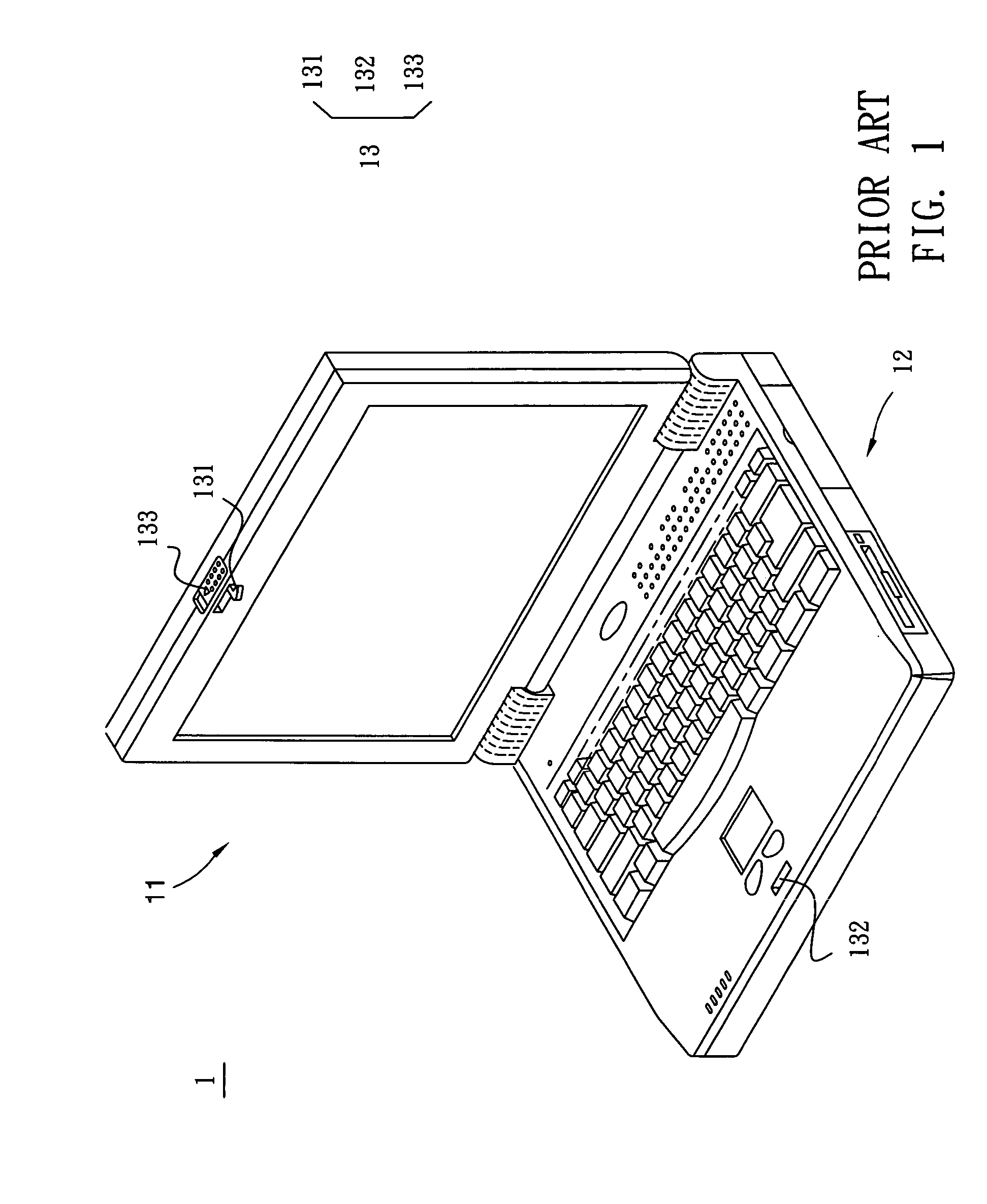
If the user unintentionally provides a too-large force, the hook 131 tends to be damaged and thus influences the operation of the locking assembly 13.
Sometimes, if the closing force is too large, the side frame of the liquid crystal display 11 may be damaged.

Method used


Image

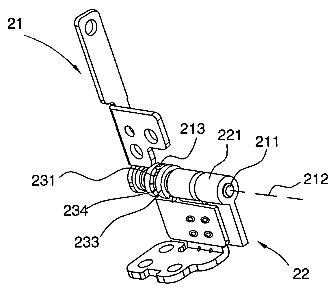
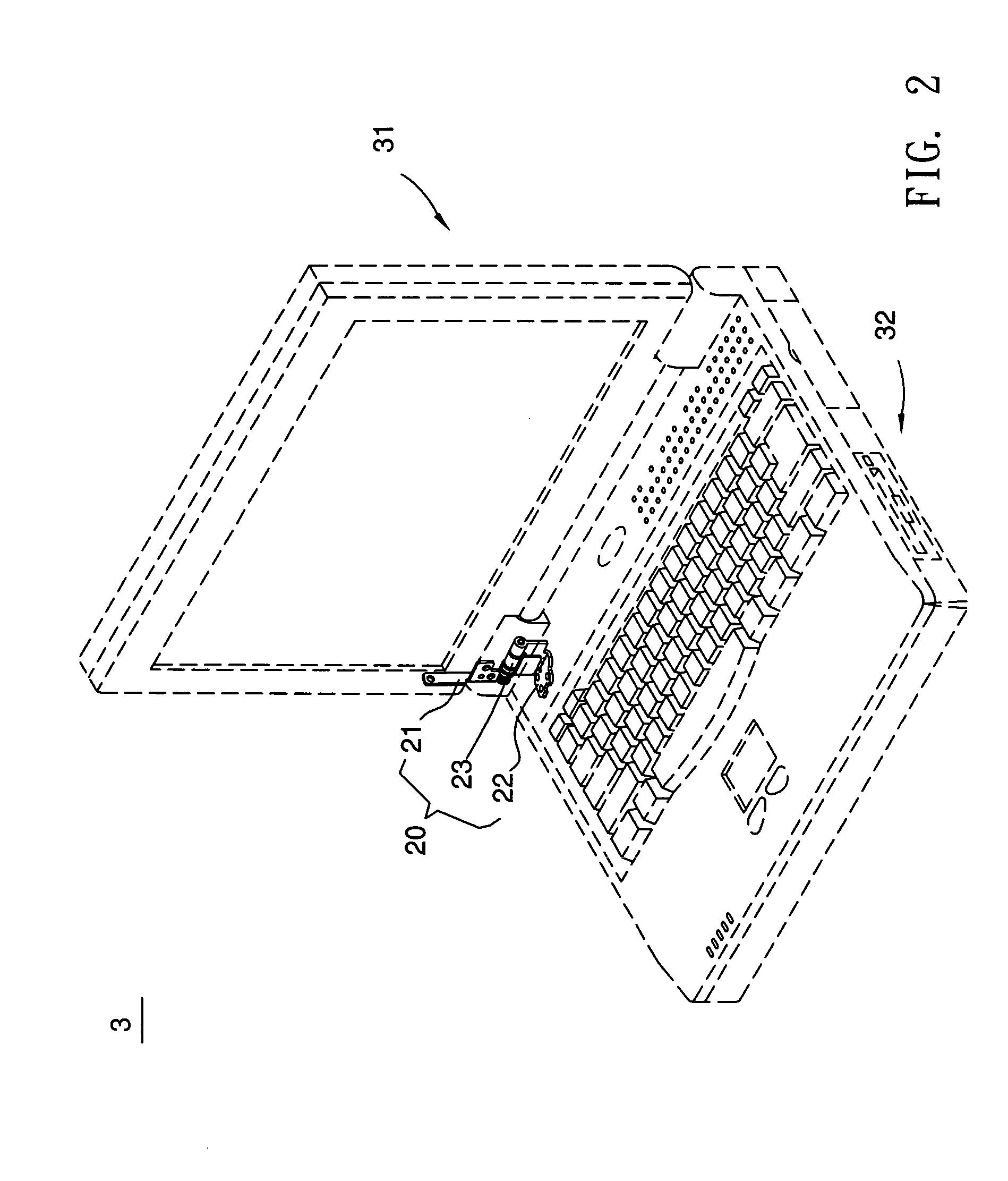
  • Multi-stage hinge assembly and electrical device
  • Multi-stage hinge assembly and electrical device
  • Multi-stage hinge assembly and electrical device

Examples


Embodiment Construction

[0020]The present invention will be apparent from the following detailed description, which proceeds with reference to the accompanying drawings, wherein the same references relate to the same elements.

[0021]First, please refer to FIG. 2 to FIG. 4 for illustrating a multi-stage hinge assembly according to a first preferred embodiment of the invention.

[0022]Referring to FIG. 2, a multi-stage hinge assembly 20 includes a first component 21, a second component 22 and a connecting portion 23. The multi-stage hinge assembly 20 is to be connected between a first shell portion 31 and a second shell portion 32 of an electrical device 3. The electrical device 3 may be a notebook computer, a digital personal assistant (PDA), or any other portable data processing apparatus. In this embodiment, for example, the electrical device 3 is a notebook computer, the first shell portion 31 may be a side frame of a LCD (Liquid Crystal Display) panel, and the second shell portion 32 may be a host shell po...


PUM


Abstract

A multi-stage hinge assembly connected between first and second shell portions includes a first component, a second component and a connecting portion. At least one part of the first component is fixed to the first shell portion. A pivot extends from one side of the first component along a rotating axis. A protrusion is disposed on the pivot. At least one part of the second component is fixed to the second shell portion. The connecting portion is disposed beside the second component and pivots on the pivot. When the first component rotates relative to the second component, the pivot or connecting portion rotates about the rotating axis. First and second trenches are disposed in the connecting portion and separate it into first and second connecting portions. The first and second trenches are connected together and have different widths. The protrusion slides in the first or second trench.

Description

BACKGROUND OF THE INVENTION[0001]1. Field of Invention[0002]The invention relates to a hinge assembly and an electrical device, and more particularly to a multi-stage hinge assembly having a multi-stage hinge structure for automatically locking a notebook computer, and an electrical device using the hinge assembly.[0003]2. Related Art[0004]Notebook computers have been widely used among the current information products because they have the main advantage of good mobility and capable of being carried by the user to anywhere according to the requirements. In the highly developed and advanced information technology, a notebook computer may serve as a mobile workstation capable of enabling the network information acquisition and transmission and the database management. So, the notebook computer is the best choice for implementing the mobile office. In addition to the consideration of the software pack, the notebook computer still has to take the human-oriented operations into important...

Claims


Application Information

Patent Timeline
Patent Type & Authority Patents(United States)
IPC IPC(8): E05D11/08G06F1/16H05K5/02
CPCE05D11/087G06F1/1616G06F1/1681G06F1/1679E05Y2900/606Y10T16/54038Y10T16/5403Y10T16/54E05Y2999/00
Inventor LIN, SAN-FENGLI, YI-CHUAN
Owner ASUSTEK COMPUTER INC
Learn More