
Simulated battery logic testing device

a logic testing and battery technology, applied in the field of test devices, can solve the problems of inability to effectively and automatically test the logic circuitry of the battery charging logic of the functional test devi

Inactive Publication Date: 2009-06-02
AVAGO TECH WIRELESS IP SINGAPORE PTE
View PDF8 Cites 7 Cited by
  • Summary
  • Abstract
  • Description
  • Claims
  • Application Information

AI Technical Summary

Benefits of technology

Provides a reliable and predictable method to test battery charging circuits and logic circuitry, ensuring proper operation and detecting errors in battery switchover and charging functionality.

Problems solved by technology

Functional test devices have been unable to effectively and automatically test battery charging logic circuitry in the past, relying on actual batteries in the test function which become unreliable after repeated use.

Method used


Image

  • Simulated battery logic testing device
  • Simulated battery logic testing device
  • Simulated battery logic testing device

Examples


Embodiment Construction

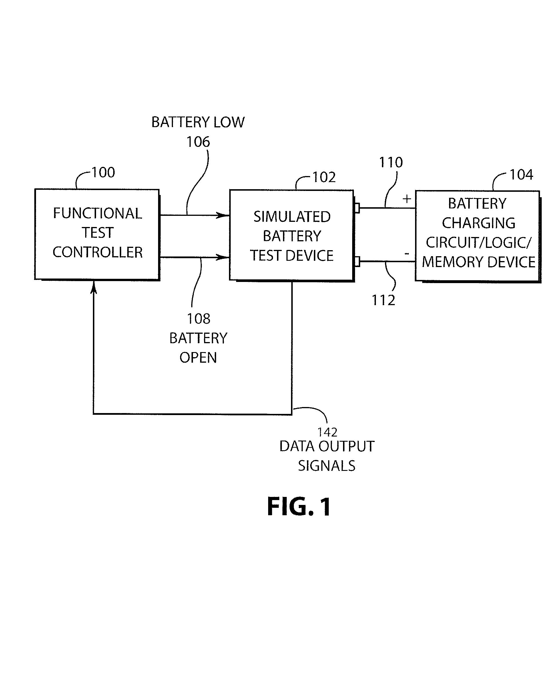
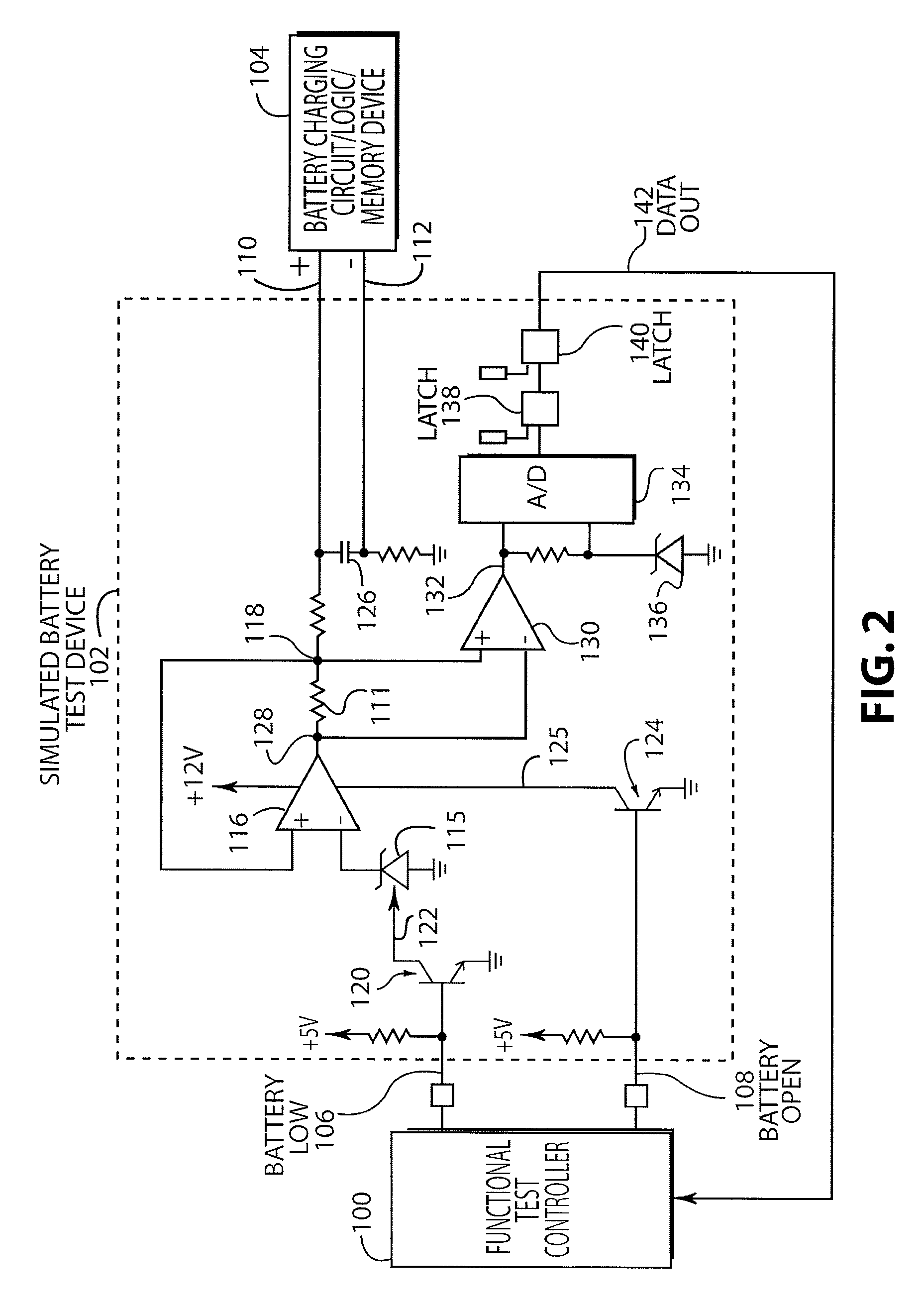
[0015]FIG. 1 is a schematic block diagram illustrating an embodiment of the invention. As shown in FIG. 1 a functional test controller 100 is operatively connected to a simulated battery test device 102. The functional test controller generates a battery low signal 106 that is applied to the simulated battery test device 102 and a battery open signal 108 that is also applied to the simulated battery test device 102. The simulated battery test device 102 is connected to a battery charging circuit / logic / memory device 104 by way of a positive terminal 110 and a negative terminal 112. The simulated battery test device 102 generates data output signal 142 that provides data to the functional test controller 100 relating to certain tests performed on the battery charging circuit / logic / memory device 104. The simulated battery test device 102 simulates the functions of a battery that would otherwise be connected to the battery charging circuit / logic / memory device 104. The simulated battery ...


PUM


Abstract

A simulated battery test device and method that is capable of testing a battery charging circuit and logic circuit to determine proper operation. An operational amplifier is used that can both source and sink current to simulate the operation of the battery. A battery low signal can be generated using the simulated battery test device to test a battery charging circuit and logic circuit in a battery low condition. In addition, a battery open signal can be generated to test the battery charging and logic circuit in a battery open condition. Charging currents are detected to determine if currents fall within an acceptable range.

Description

BACKGROUND OF THE INVENTION[0001]a. Field of the Invention[0002]The present invention pertains generally to test devices and more particularly to a simulated battery logic testing device.[0003]b. Description of the Background[0004]Many devices use battery backups to protect against electrical line failure. Battery charging circuits in such systems include logic that controls the charging circuit. For example, voltage and current regulation are controlled in the battery charging circuit, as well as detection of electrical line loss and switchover to battery operation. If the logic in the battery charging circuit fails, a battery switchover may not occur when needed, or a battery may not be charged as needed. Functional test devices have been unable to effectively and automatically test battery charging logic circuitry in the past, relying on actual batteries in the test function which become unreliable after repeated use.SUMMARY OF THE INVENTION[0005]An embodiment may therefore compr...

Claims


Application Information

Patent Timeline
Patent Type & Authority Patents(United States)
IPC IPC(8): G01R31/36G06F19/00
CPCG01R31/2848
Inventor HORNING, RANDALL F.TANG, EDDE TIN SHEKFAFACH, JR., DEL
Owner AVAGO TECH WIRELESS IP SINGAPORE PTE
Learn More