Light scanning apparatus and image forming apparatus using the light scanning apparatus

a light scanning and light scanning technology, applied in the field of light scanning apparatus and image forming apparatus, can solve the problem that the reproducibility of the image cannot be preferably maintained, and achieve the effect of preventing a fluctuation in light intensity, high color saturation, and preferable reproducibility of the imag

Inactive Publication Date: 2009-06-02
CANON KK
View PDF3 Cites 14 Cited by
  • Summary
  • Abstract
  • Description
  • Claims
  • Application Information

AI Technical Summary

Benefits of technology

[0020]It is an object of the present invention to provide a light scanning apparatus capable of preventing a fluctuation in light intensity on a photosensitive drum surface with respect to a fluctuation in environment and a fluctuation in wavelength, keeping preferable reproducibility of an image and satisfying an image quality exhibiting high color saturation, and to provide an image forming apparatus using this light scanning apparatus.
[0022]According to the present invention, it is possible to attain the light scanning apparatus capable of preventing the fluctuation in the light intensity on the photosensitive drum surface with respect to the fluctuation in the environment and the fluctuation in the wavelength, preferably keeping the reproducibility of the image and obtaining the image quality exhibiting the high color saturation, and to attain the image forming apparatus using this light scanning apparatus.

Problems solved by technology

As a result, such a problem arises that reproducibility of the image cannot be preferably maintained.

Method used


Image

  • Light scanning apparatus and image forming apparatus using the light scanning apparatus
  • Light scanning apparatus and image forming apparatus using the light scanning apparatus
  • Light scanning apparatus and image forming apparatus using the light scanning apparatus

Examples


first embodiment

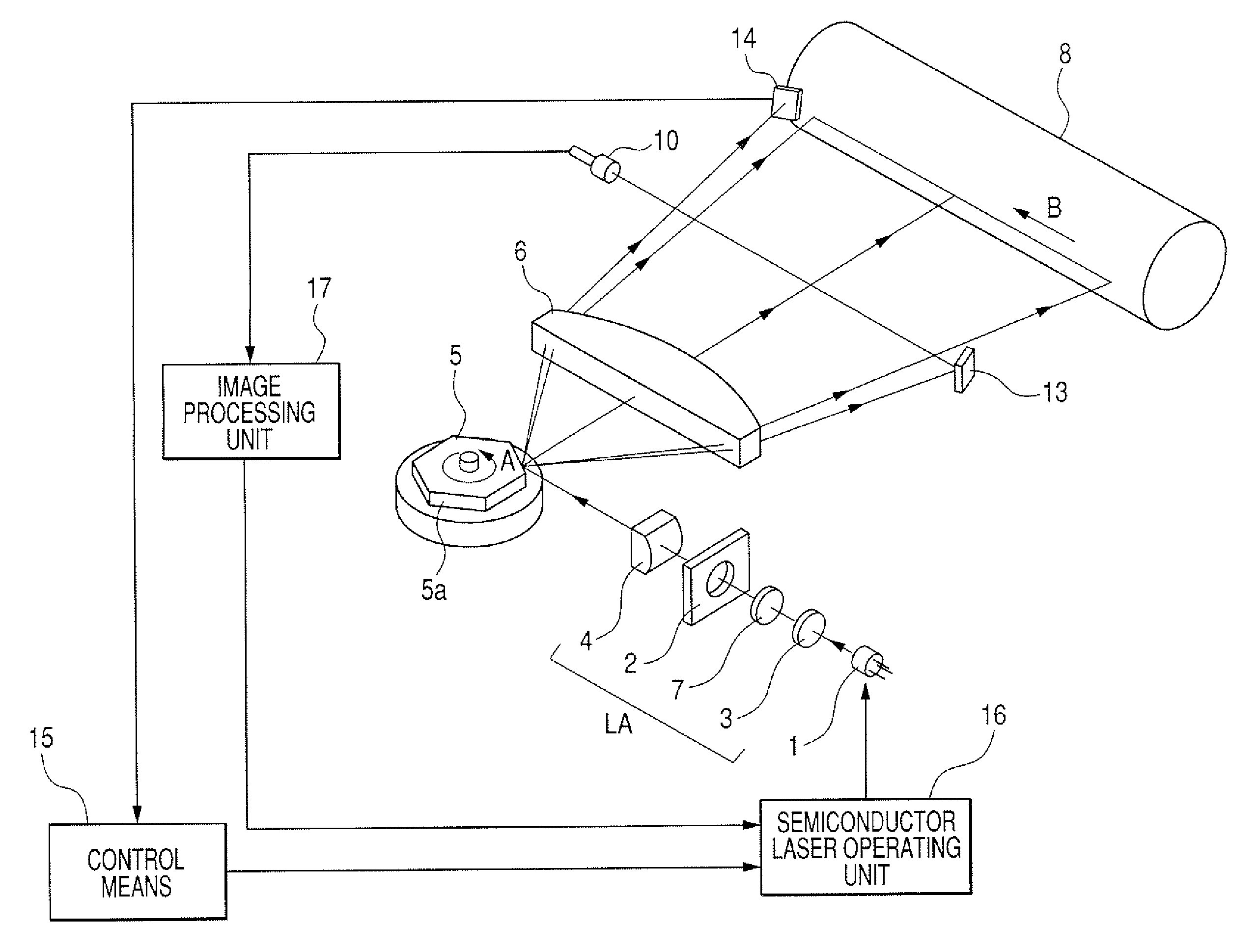
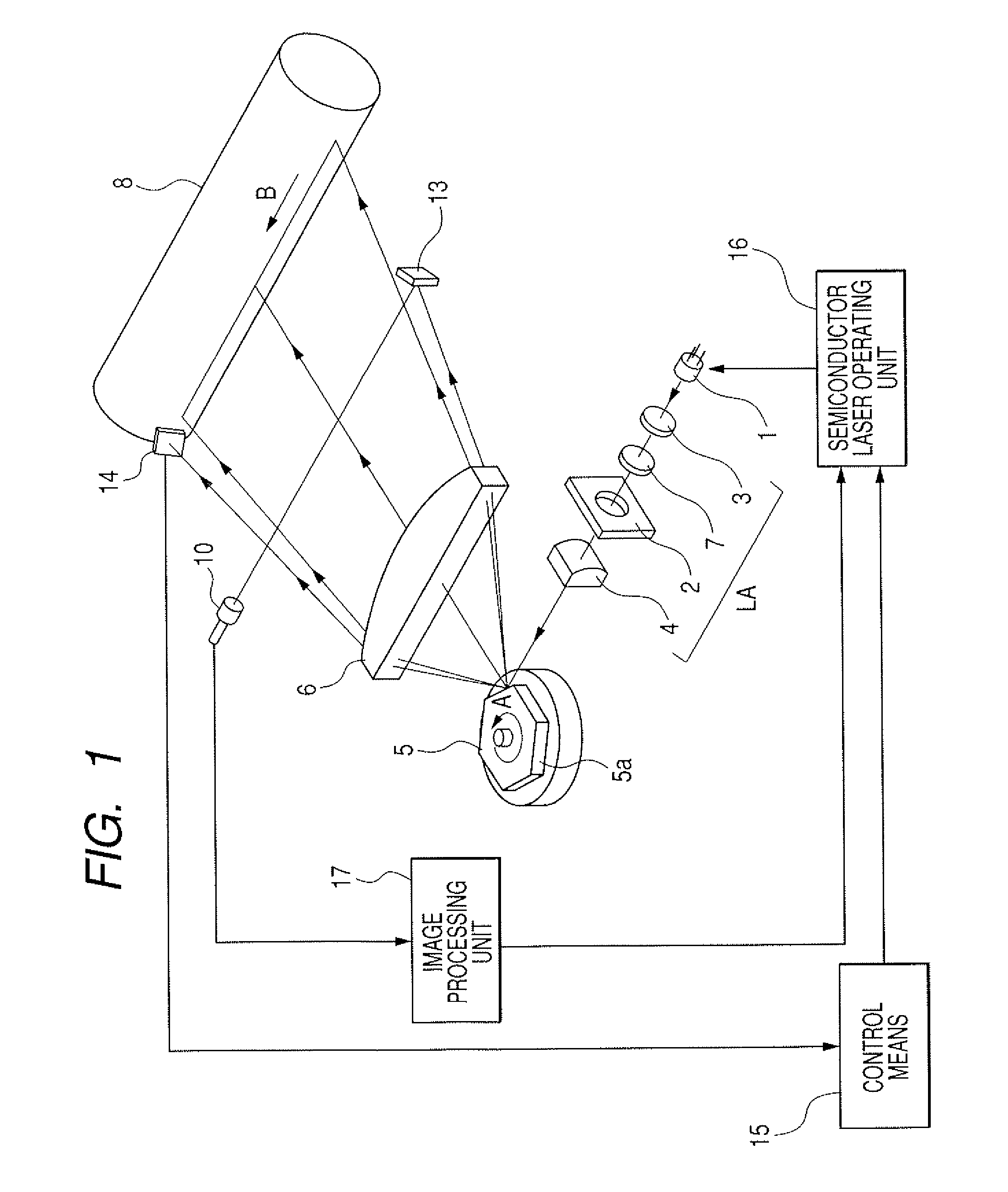
[0042]FIG. 1 is a principal view (a principal perspective view) showing an operational principle of a light scanning apparatus in a first Embodiment of the present invention.

[0043]It should be noted that, in the following discussion, a main scanning direction connotes a direction perpendicular to an axis of rotation of a rotary polygon mirror and to an optical axis of an imaging optical system. A subscanning direction represents a direction parallel to the axis of rotation of the rotary polygon mirror. Further, a main scanning section defines a plane covering the main scanning direction and the optical axis of the imaging optical system. Further, the subscanning section is a section perpendicular to a main scanning section.

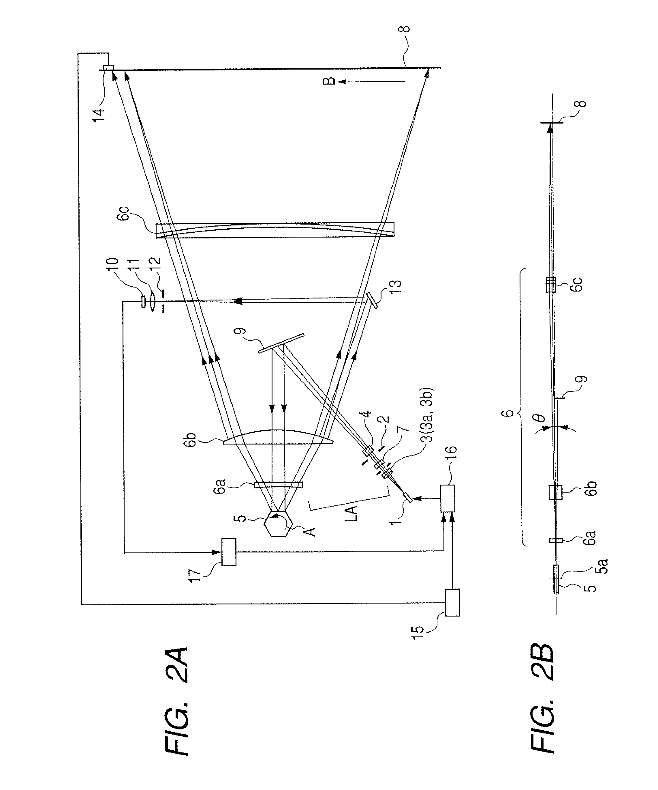
[0044]FIGS. 2A and 2B are principal sectional views each showing a specific example of the first Embodiment of the present invention.

[0045]FIG. 2A is the principal sectional view (the main scanning sectional view) in the main scanning direction, and FIG. 2B is the...

second embodiment

[0090]FIG. 5 is a principal view showing the principle of the light scanning apparatus in a second Embodiment of the present invention. FIG. 6 is a principal sectional view illustrating a specific example of the second Embodiment of the present invention. FIG. 7 is a graph showing field curvatures in the main scanning direction and in the subscanning direction in the second Embodiment of the present invention. In FIGS. 5 and 6, the same components as those depicted in FIGS. 1 and 2 are marked with the same numerals.

[0091]A different point of the second Embodiment from the first Embodiment discussed above is that the light intensity detection light beams deflected by the light deflector 5 are guided to the light intensity detection sensor 14 without passing through the imaging optical system 6. For example, the light intensity detection sensor 14 is disposed between the light paths of the light source means 1 and of the light deflector 5 (FIG. 6), or disposed in a position for detect...

third embodiment

[0113]FIG. 10 is a principal perspective view of the light scanning apparatus in a third Embodiment of the present invention. In FIG. 10, the same components as those depicted in FIG. 1 are marked with the same numerals.

[0114]A different point of the third Embodiment from the second Embodiment is that the configuration for detecting the light intensity is simplified. Therefore, the light intensity detection sensor 14 is disposed in the vicinity of the semiconductor laser 1, and a correction plate 19 is disposed anterior to the light intensity detection sensor 14.

[0115]Other configurations and optical action are substantially the same as those in the second Embodiment, whereby the same effects are acquired.

[0116]In FIG. 10, reference numeral 18 represents a half mirror serving as a beam splitting means. The half mirror 18 is provided in the light path between the semiconductor laser 1 and the incidence optical system LA. The half mirror 18 performs a role of splitting the light beams...


PUM


Abstract

A light scanning apparatus including a semiconductor laser which emits a light beam having a wavelength equal to or less than 450 nm, an incidence optical system which makes the light beam, emitted from the semiconductor laser, incident on a deflector for scanning in deflection, an imaging optical system which images the light beam scanned in deflection by the deflector to a surface to be scanned, a light intensity detector which detects fluctuations in spectral transmittances of the incidence optical system and of the imaging optical system, which are caused as a concomitant of a fluctuation in wavelength of the light beam which is emitted from the semiconductor laser and passes through the incident optical system and the imaging optical system, and an automatic power controller which automatically controls a light emission output of the semiconductor laser on the basis of a detection value detected by the light intensity detector.

Description

[0001]This application claims the benefit of Japanese Patent Application No. 2005-280432, filed Sep. 27, 2005, which is hereby incorporated by reference herein in its entirety.BACKGROUND OF THE INVENTION[0002]1. Field of the Invention[0003]The present invention relates a light scanning apparatus and an image forming apparatus using this light scanning apparatus, and is suited to an image forming apparatus, such as a laser beam printer and a digital copying machine that have an electrophotographic process, and a multi-function printer.[0004]2. Description of the Related Art[0005]According to the prior art, in a light scanning apparatus, such as a laser beam printer (LBP), light beams optically modulated and emitted from a light source means are periodically deflected by a light deflector (a polygon mirror, etc.) corresponding to image signals. The deflected light beams are converged in a spot-like shape on a photosensitive drum through a light scanning optical system having a charact...

Claims


Application Information

Patent Timeline
Patent Type & Authority Patents(United States)
IPC IPC(8): G02B26/08
CPCG02B26/127
Inventor TANIMURA, KENSHIMOMURA, HIDEKAZUTAKIZAWA, TOKUJI
Owner CANON KK
Why Eureka
Try Eureka