
Liquid container, sub tank, liquid discharge apparatus, liquid supply apparatus, and imaging apparatus

a technology of liquid supply apparatus and sub-tank, which is applied in the direction of packaging, printing, transportation and packaging, etc., can solve the problems of inability to realize sealing, fluctuation of liquid level of ink in the sub-tank, and viscosity of the liquid adhering to the entrance portion of the supply exhaust path

Active Publication Date: 2009-06-02
RICOH KK
View PDF28 Cites 39 Cited by
  • Summary
  • Abstract
  • Description
  • Claims
  • Application Information

AI Technical Summary

Benefits of technology

The present invention provides a liquid container and a liquid supply apparatus for an imaging apparatus that can reduce the inflow of liquid into the air flow path of a liquid discharge member, and can supply liquid to the liquid discharge member according to the liquid consumption amount. The invention also provides a sub tank that can generate negative pressure to stabilize liquid discharge characteristics. The invention improves the reliability of supplying liquid to the liquid discharge member, and ensures stable image formation. The invention simplifies the structure of the liquid supply apparatus and the imaging apparatus.

Problems solved by technology

However, in this case, when the imaging apparatus is not used for a long period of time, ink adhering to the entrance portion of the supply exhaust path may grow viscous and the path may be sealed by this ink.
However, even in this prior art example, when ink enters the exhaust unit, the same effect as that described above may occur when the imaging apparatus is not used for a long period of time; that is, the ink at the entrance portion of the exhaust unit may grow viscous and may seal the exhaust path.
However, when the imaging apparatus is in use, ink may enter the air flow path due to movement of the carriage which causes the liquid level of ink in the sub tank to fluctuate.
As a result, ink may adhere to a sealing member of an air releasing valve that is used for opening and closing the air flow path, and the ink may grow viscous so that sealing may not be realized and the air flow path may be blocked.
Thereby, the structure of the sub tank may be quite complicated.
Similarly, in the sub tank of Japanese Patent Laid-Open Publication No. 2002-86748, since a flexible container that accommodates ink is implemented inside the case, and the flexible container is expanded and contracted by suction / atmospheric release of the case, the structure of the negative pressure generation unit may be complicated.
In a case where a restoration operation is performed in a liquid discharge apparatus including a conventional sub tank as described above, bubbles are likely to be generated when air is present in the sub tank so that the nozzles may easily come off.
Also, it is noted that control of the negative pressure may be difficult, and ink discharge characteristics may be susceptible to fluctuations.
Further, when the sub tank implements a flexible film member and an elastic member to generate a negative pressure as is described above, the capacity of the sub tank changes, and thereby, the amount of ink remaining in the sub tank may not be accurately detected.
When such hysteresis occurs, instability is created in the control of the negative pressure, and the liquid discharge characteristics become unstable.

Method used


Image

  • Liquid container, sub tank, liquid discharge apparatus, liquid supply apparatus, and imaging apparatus
  • Liquid container, sub tank, liquid discharge apparatus, liquid supply apparatus, and imaging apparatus
  • Liquid container, sub tank, liquid discharge apparatus, liquid supply apparatus, and imaging apparatus

Examples


Embodiment Construction

[0085]In the following, preferred embodiments of the present invention are described with reference to the accompanying drawings.

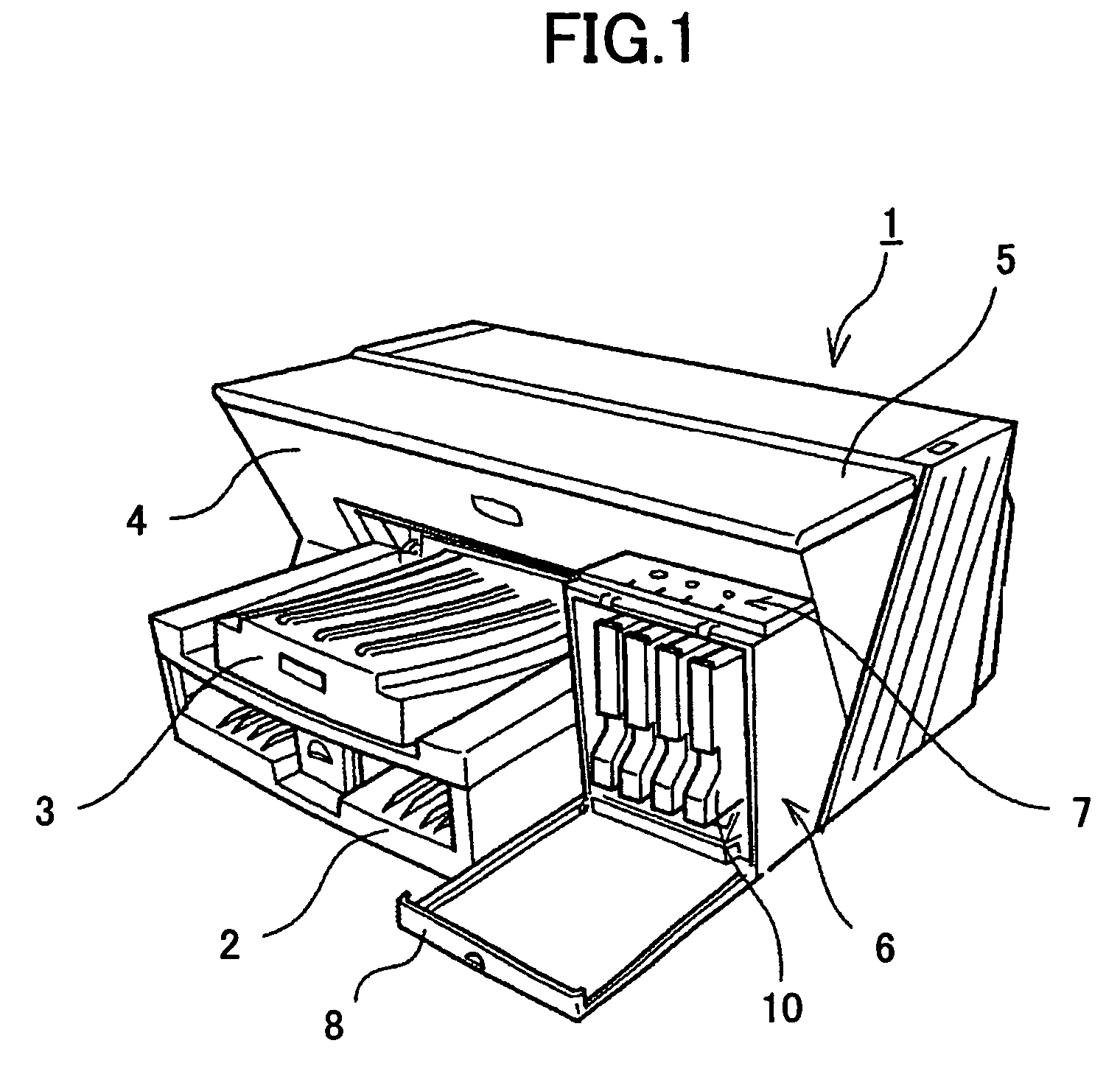
[0086]FIG. 1 shows a perspective view of an inkjet recording apparatus according to an embodiment of the present invention that is viewed from the front side. The ink jet recording apparatus of FIG. 1 implements a liquid container and a liquid supply apparatus that correspond to embodiments of the present invention.

[0087]As is shown in this drawing, the inkjet recording apparatus includes an apparatus main body 1, a paper feed tray 2 that is attached to the apparatus main body 1, and a paper delivery tray 3 that is also attached to the apparatus main body 1. The paper feed tray 2 supplies paper to the apparatus, and the paper delivery tray 3 stacks paper having an image recorded (formed) thereon. Also, at one side of a front portion 4 of the apparatus, a cartridge load unit 6 that protrudes from the front portion 4 and is positioned lower than a top portio...


PUM


Abstract

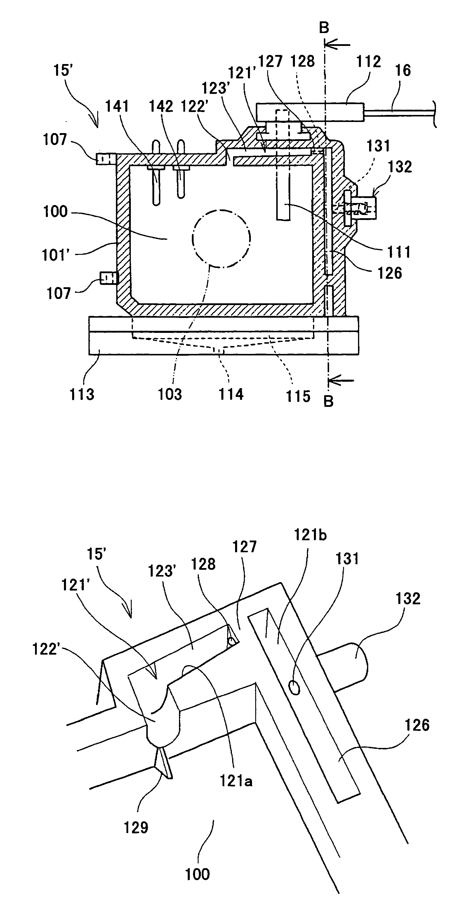
A sub tank is provided that includes a case at which an air flow path is formed, the air flow path including an entrance flow path portion that is connected to an ink accommodating portion of the case, and a cross flow path portion that continues from the entrance flow path portion. The cross flow path portion extends in an upper diagonal direction with respect to a reference plane corresponding to the ink liquid level at a standstill state. Another sub tank is provided that includes a case forming an ink accommodating portion, on which case a flexible film member is attached through bonding or welding to seal an opening of the ink accommodating portion and to form one side of the sub tank. A spring is disposed within the ink accommodating portion between the case and the flexible film member, the spring forcing the flexible film member outward.

Description

TECHNICAL FIELD[0001]This disclosure relates generally to a liquid container, a sub tank, a liquid discharge apparatus, a liquid supply apparatus, and an imaging apparatus.BACKGROUND ART[0002]In an inkjet recording apparatus that may be applied to an imaging apparatus such as a printer, a facsimile machine, a copier, and a plotter, for example, a small capacity sub tank is implemented on a carriage, a large capacity main cartridge (main tank) is implemented in a main body of the apparatus, and an apparatus for supplying ink from the main cartridge at the apparatus main body to the sub tank is provided.[0003]In Japanese Patent Laid-Open Publication No. 2003-53993, a sub tank including a movable part that is made of a deformable film sheet, a spring that is adapted to supply negative pressure, and a supply / exhaust path that supplies ink and discharges mixed gas is provided. In this sub tank, the supply / exhaust path is positioned so that interference with the movable part and the sprin...

Claims


Application Information

Patent Timeline
Patent Type & Authority Patents(United States)
IPC IPC(8): B41J2/175B65D
CPCB41J2/17513B41J2/1752B41J2/17553B41J2/17556B41J2/17566B41J2/17503
Inventor HORI, EISUKETOKUNO, TOSHIROHKANEKO, TETSUYASATOH, KENJI
Owner RICOH KK
Learn More