
Method and apparatus for stop log slot/guide sealing surface cleaning

a technology of sealing surface and stop log, which is applied in the direction of cleaning equipment, cleaning using liquids, vehicle cleaning, etc., can solve the problems of increasing risk and legal requirements, reducing the number of workers required, and leaking paths, so as to reduce the time required to clean, reduce the number of workers required, and reduce the effect of risk

Inactive Publication Date: 2009-06-02
WRIGHT SR BRADLEY RUSSELL
View PDF1 Cites 0 Cited by
  • Summary
  • Abstract
  • Description
  • Claims
  • Application Information

AI Technical Summary

Benefits of technology

The machine significantly reduces cleaning time and worker numbers, lowers risk, and allows for continuous operation, thereby reducing downtime and costs while ensuring safer and more efficient cleaning of stop log seating surfaces.

Problems solved by technology

Marine life such as barnacles, shell fish and other debris trapped under seals can create a leak path by creating a rough seating surface or cutting or tearing the seal material.
The use of divers although effective is inherently dangerous, time consuming and expensive.
The cleaning of stop log slots / guides also constitutes a confined space dive further increasing risk and legal requirements.
In spite of industrial safety regulations dive accidents continue to occur on a regular basis and do claim lives.
Shortcuts or mistakes in this area occur too often and can have fatal consequences.
The diver is suspended or floating in water and while he scrapes or cuts the attached marine life from the seating surface of the slot, making the job more difficult and time consuming.
The diver force that is applied in scraping is also limited by the physical strength and endurance of the diver.
Visibility for the diver is commonly low in this environment and gets worse during the cleaning operation due to stirring up silt and mud.
Although these tools can be effective, the supporting equipment is expensive, they are operated by divers, and can be a hazard to the diver himself.
Hydrolazers require extreme caution and protective gear since the high pressure water jet can cut or inject into the diver and injure or kill them.
Operating a hydrolazer while suspended in water adds to the risk.
There is also the possible risk to the diver from sharks, barracuda, alligators etc.

Method used


Image

  • Method and apparatus for stop log slot/guide sealing surface cleaning
  • Method and apparatus for stop log slot/guide sealing surface cleaning
  • Method and apparatus for stop log slot/guide sealing surface cleaning

Examples


Embodiment Construction

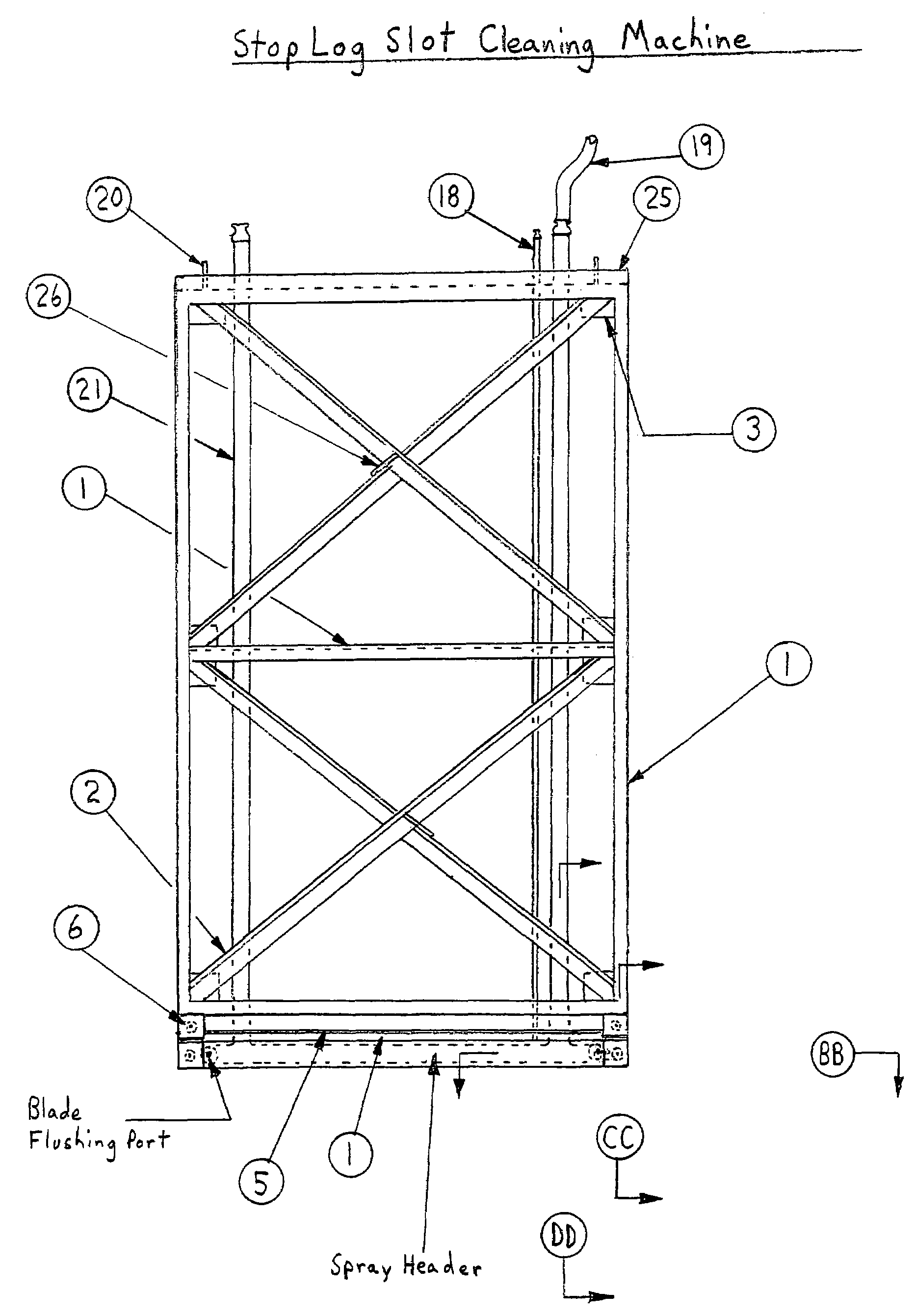
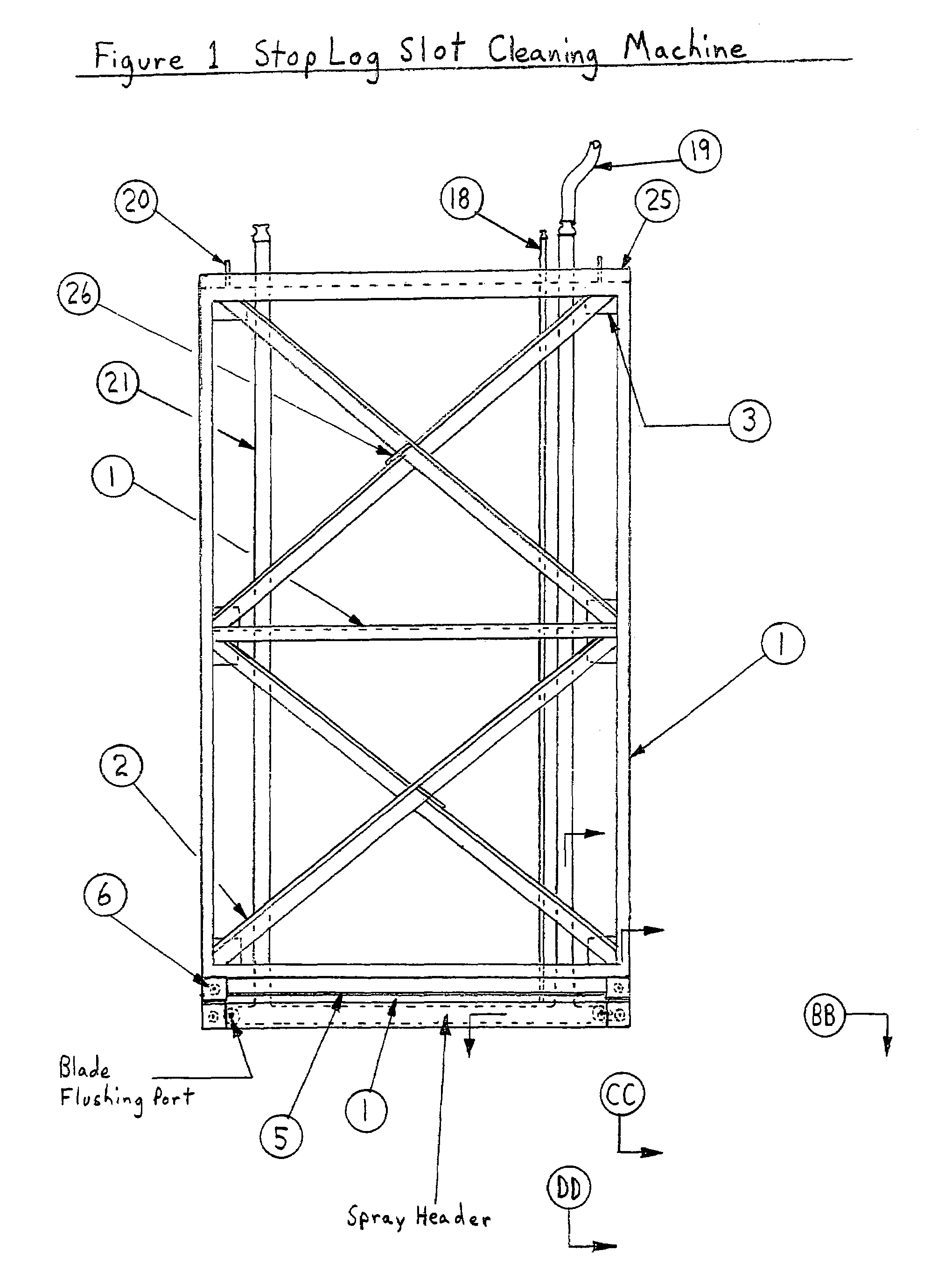
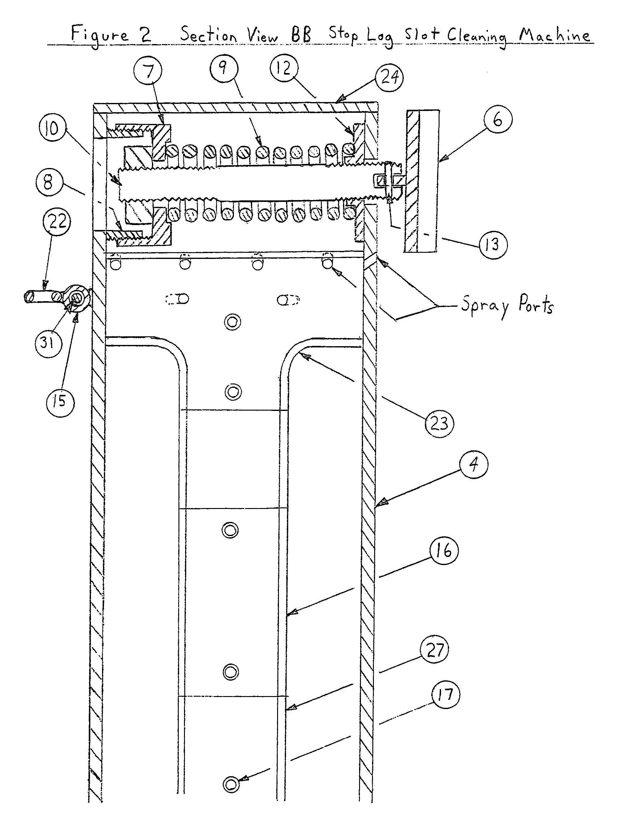
[0028]Turning first to FIG. 1, there is illustrated an overall basic front view of the stop log slot cleaning machine 100 in accordance with the present invention and showing locations of section views BB, CC, and DD. The stop log slot cleaning machine 100 comprises structural frame 102 constructed of, for example, structural steel components 1, 2, 3, 4, 5, 24, 25, and 26, with lifting lugs 20, water supply hoses 19, water supply pipes 20, optional air supply line 18, adjustable spring loaded scraper blades 6 (shown in details on FIG. 2), and phantom / dotted lines showing the outline of the spray header 103 (details shown in FIG. 3). The frame 102 is preferably constructed of structural steel held together using welds, bolts and / or by means of another fastener system and provides a structure to attach the scraper blades 6 and to hold them in position against the seating surface of the stop log slot being cleaned. Frame 102 further provides an amount of weight necessary to produce dow...


PUM


Abstract

A stop log slot / guide cleaning method and apparatus is disclosed as a frame with attached scraping or scrubbing devices attached in locations that will contact and shear off attached marine life or debris. A flushing system that using water or compressed air or both attached and located on the frame pushes the removed or loose debris off of the stop log slot / guide seating surfaces as the frame is lowered into or removed from the slot leaving clean flat sealing surfaces for the stop log seals to seal against.

Description

REFERENCE TO RELATED APPLICATION[0001]Priority under 35 U.S.C. § 119(e) is claimed from U.S. Provisional Application No. 60 / 581,332, filed Jun. 18, 2004, the entire contents of which are incorporated by reference herein.BACKGROUND OF INVENTION[0002]The present invention relates to the industrial cleaning of stop log slots, sometimes referred to as stop log guides, by removing and flushing away both attached and loose debris such as marine life silt from the stop log seating surfaces using a frame and attachments without the need of human divers. Stop logs are commonly used in industrial applications such as power plant intake cavities, canals, and discharge conduits, tunnels and piping to provide a barrier or dam to allow water to drained or pumped out of an area or structure that is otherwise flooded. The areas or structures are normally drained for the purpose of allowing workers to enter the space and perform maintenance activities that either can not or are not cost effective to...

Claims


Application Information

Patent Timeline
Patent Type & Authority Patents(United States)
IPC IPC(8): A47L1/00B08B1/00B08B3/02B08B5/02
CPCB08B1/008B08B3/024B08B5/02B08B1/30
Inventor WRIGHT, SR., BRADLEY RUSSELL
Owner WRIGHT SR BRADLEY RUSSELL
Learn More