
Optical filter for flash lamps in pulsed thermal imaging

a technology of optical filter and flash lamp, which is applied in the field of optical filter for flash lamp, can solve the problems of inability to use pulsed thermal imaging, inability to reliably test materials, and major hardware problems of infrared radiation from flash lamps, so as to reduce infrared radiation and reduce flash energy in visible wavelengths

Active Publication Date: 2009-05-26
UCHICAGO ARGONNE LLC +1
View PDF10 Cites 7 Cited by
  • Summary
  • Abstract
  • Description
  • Claims
  • Application Information

AI Technical Summary

Benefits of technology

The patent describes an optical filter for flash lamps used in pulsed thermal imaging. The filter blocks infrared wavelengths that are sensitive to an infrared camera, while allowing visible wavelengths to pass through. This helps to accurately detect surface temperature during the imaging test. The filter is made from a borosilicate optical material that has a high optical transmission in the visible wavelengths and low transmission in the infrared wavelengths. The filter can be made from a stack of multiple plates to reduce the infrared radiation from the flash by a significant amount while maintaining the flash energy in the visible wavelengths. The filter ensures accurate and usable data without errors introduced by flash reflection and residual heating effects.

Problems solved by technology

Infrared radiation from flash lamp is a major hardware problem in one-sided pulsed thermal imaging.
However, this has not been of significant concern for most thermography users because most applied for NDE detection of large / severe defects (e.g., delaminations) in slow transient materials such as polymer matrix composites.
Pulsed thermal imaging is not reliable (or cannot be used) to test these materials.
This practice is not desirable for some materials such as TBCs.
However, water is not an efficient filtering medium for the wavelengths used in the state-of-the-art infrared cameras because these cameras are designed for remote sensing so they must avoid the water (moisture) absorption bands to achieve long-distance imaging capability.
This device, besides its complex operation procedure, does not allow the camera to take image data during the flash period, but it does eliminate residual heating problem.
However, reducing the flash duration will also reduce the flash power; the demonstrated 2.5-ms flash retains only about 50% power of the full flash.
In addition, this device does not allow for thermal imaging during the flash period and, since the flash tube is still hot after current is cut off, residual-heat radiation still remains.
Thus, none of the attempts to control radiation from the flash lamp has proven to be totally effective.

Method used


Image

  • Optical filter for flash lamps in pulsed thermal imaging
  • Optical filter for flash lamps in pulsed thermal imaging
  • Optical filter for flash lamps in pulsed thermal imaging

Examples


Embodiment Construction

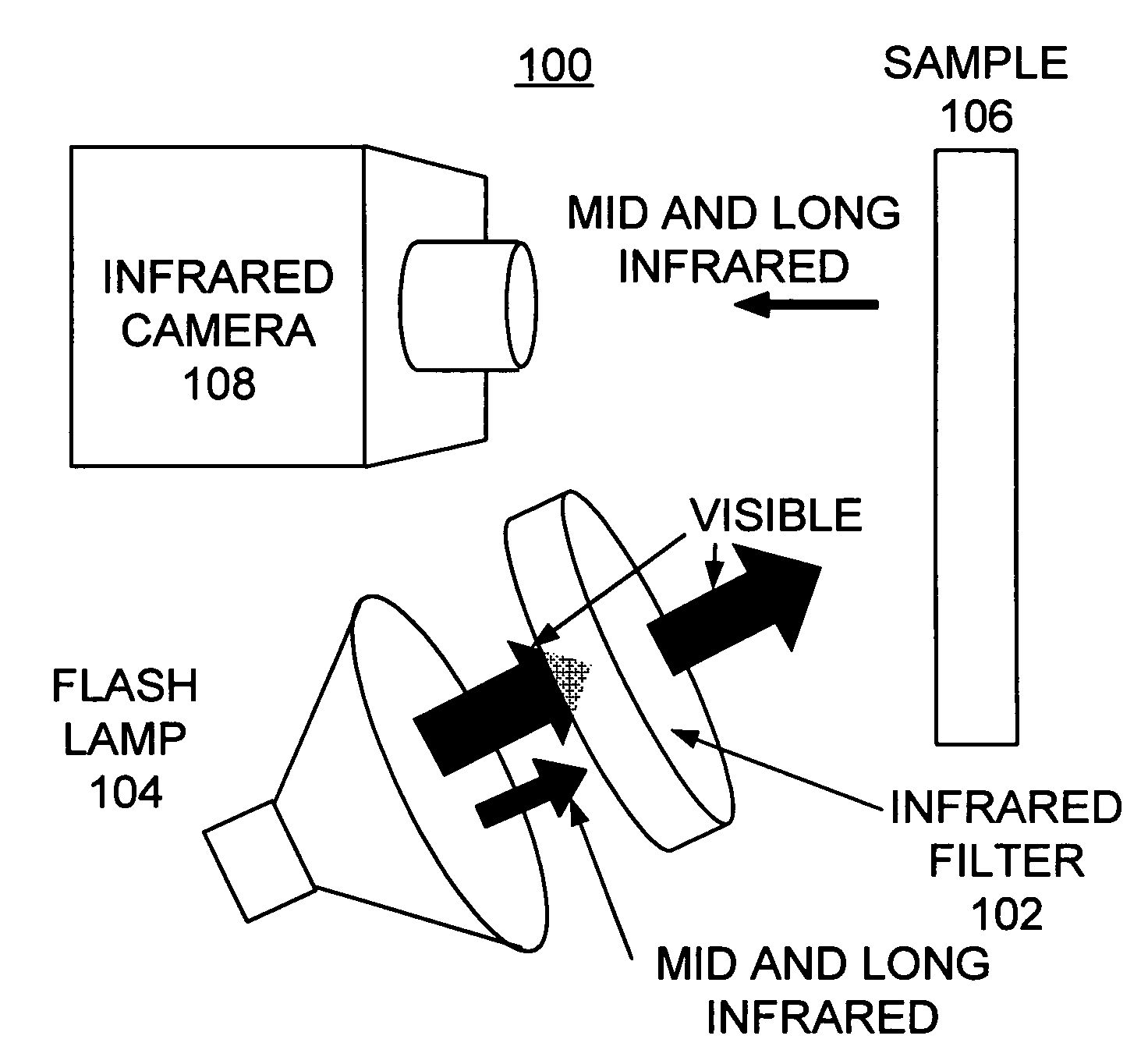
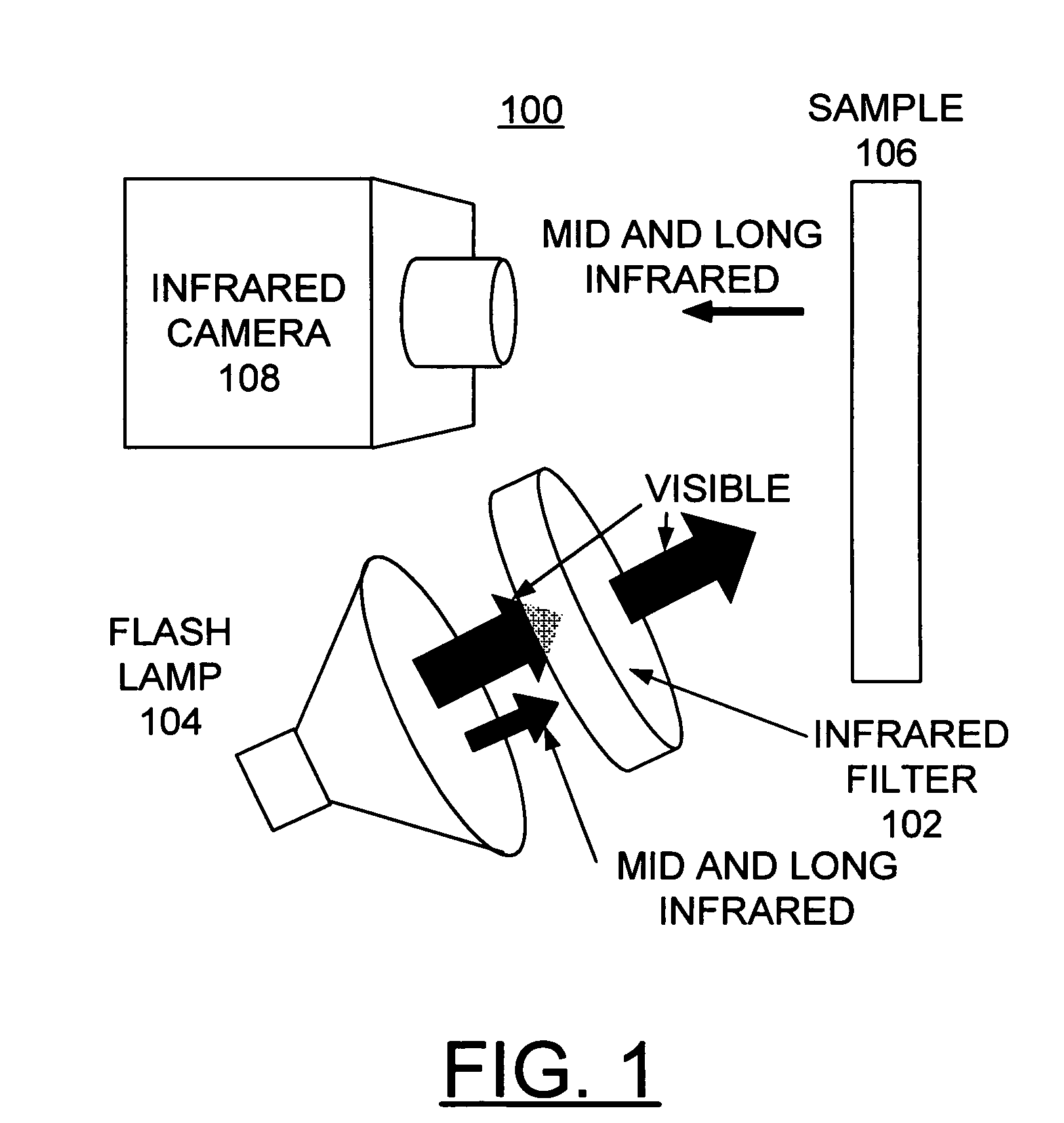
[0028]Having reference now to the drawings, FIG. 1 illustrates a pulsed thermal imaging apparatus generally designated by the reference numeral 100 including an invented infrared filter 102 in accordance with the preferred embodiment. Thermal imaging system 100 includes a flash lamp 104 providing a pulse of thermal energy for heating a first surface of the sample 106. Thermal imaging system 100 includes, for example, a high-resolution and high-sensitivity infrared camera 108, for example, with 256×256 pixel focal plane array of infrared sensors. Infrared camera 108 is positioned on the same side of the sample 102 as the flash lamps 104.

[0029]In accordance with features of the invention, the infrared filter 102 in accordance with the preferred embodiment substantially eliminates mid and long infrared radiation from the flash lamp 104 so that substantially only a visible light pulse is applied to the sample 106.

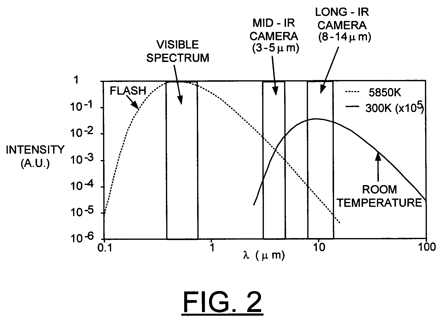
[0030]Emission of thermal radiation in pulsed thermal imaging can be estim...


PUM

PropertyMeasurementUnit
thickaaaaaaaaaa
wavelengthsaaaaaaaaaa

Abstract

An optical filter made from a borosilicate optical material is provided for flash lamps used in pulsed thermal imaging. The filter substantially eliminates the infrared radiation from flash lamps to allow for accurate detection of surface temperature during entire pulsed thermal imaging tests.

Description

[0001]The United States Government has rights in this invention pursuant to Contract No. W-31-109-ENG-38 between the United States Government and Argonne National Laboratory.FIELD OF THE INVENTION[0002]The present invention relates to an optical filter for flash lamps used in pulsed thermal imaging.DESCRIPTION OF THE RELATED ART[0003]Pulsed thermal imaging is widely used for nondestructive evaluation (NDE) of advanced materials and components. The premise is that the flow of heat from the surface of a solid is affected by internal flaws such as disbonds, voids or inclusions. In pulsed thermal imaging, optical radiation (visible light) is used to heat the surface of the sample, and an infrared camera to detect changes in the surface temperature as the surface cools. Material properties or flaws within the sample can be derived from the measured surface temperature data during and after the pulsed heating. Photographic flash lamps are the most commonly used pulsed radiative sources fo...

Claims


Application Information

Patent Timeline
Patent Type & Authority Patents(United States)
IPC IPC(8): F21V9/04G01B5/16G01N25/72
CPCG02B5/208
Inventor SUN, JIANGANG
Owner UCHICAGO ARGONNE LLC
Learn More