
Engine speed controller having PI gains set by engine speed and engine speed error

a technology of engine speed and speed error, which is applied in the direction of electric control, speed sensing governor, speed sensing device, etc., can solve the problems of inability to control engine speed with repeatable accuracy, inability to achieve output torque, so as to improve the regulation of engine speed and improve the effect of engine speed

Active Publication Date: 2009-05-26
INT ENGINE INTPROP CO LLC
View PDF12 Cites 23 Cited by
  • Summary
  • Abstract
  • Description
  • Claims
  • Application Information

AI Technical Summary

Benefits of technology

[0009]The present invention relates to an improvement in the PI (proportional-integral) control strategy for ameliorating, and ideally eliminating, observed inconsistencies, instabilities, and loss of accuracy in situations when engine speed is being limited by the engine controller, either on its own initiative or when acting on a speed limiting request from an associated controller like those mentioned before. The improvement provides noticeably better regulation of engine speed at high idle and at low speeds where high torque must be delivered, such as at vehicle launch.

Problems solved by technology

While control of individual devices, like fuel injectors, EGR valves, or turbocharger vanes for example, can be accomplished with precision, the cumulative effect of controlling each individual device when the engine is in a dynamic state of operation may at times tend to cause temporary disturbances such as transient oscillations, perturbations, overshoots, and the like, in certain operating parameters like engine speed and torque.
High idle speed is the maximum engine speed that the controller will allow and at that speed, flywheel torque is zero, meaning that the controller is causing the engine to run at that speed while developing only enough torque to overcome friction and pumping losses so that no output torque is available at the flywheel.
It has been discovered engine speed may not always be controlled with repeatable accuracy in certain situations and that some instability and / or loss of accuracy may become noticeable.

Method used


Image

  • Engine speed controller having PI gains set by engine speed and engine speed error
  • Engine speed controller having PI gains set by engine speed and engine speed error
  • Engine speed controller having PI gains set by engine speed and engine speed error

Examples


Embodiment Construction

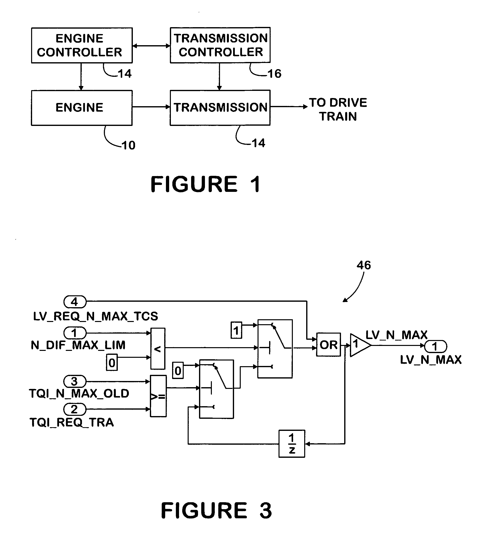
[0035]FIG. 1 shows a portion of the powertrain of a truck comprising a diesel engine 10 and a transmission 12 that couples the engine flywheel through a drivetrain to driven wheels.

[0036]A processor-based engine controller 14 that is part of an engine control system processes data from various sources to develop various control data for controlling various aspects of engine operation. The data processed by controller 14 may originate at external sources, such as sensors, and / or be generated internally.

[0037]A processor-based transmission controller 16 is associated with transmission 14. The two controllers 14, 16 are able to communicate with each other via an on-board communication network in the truck.

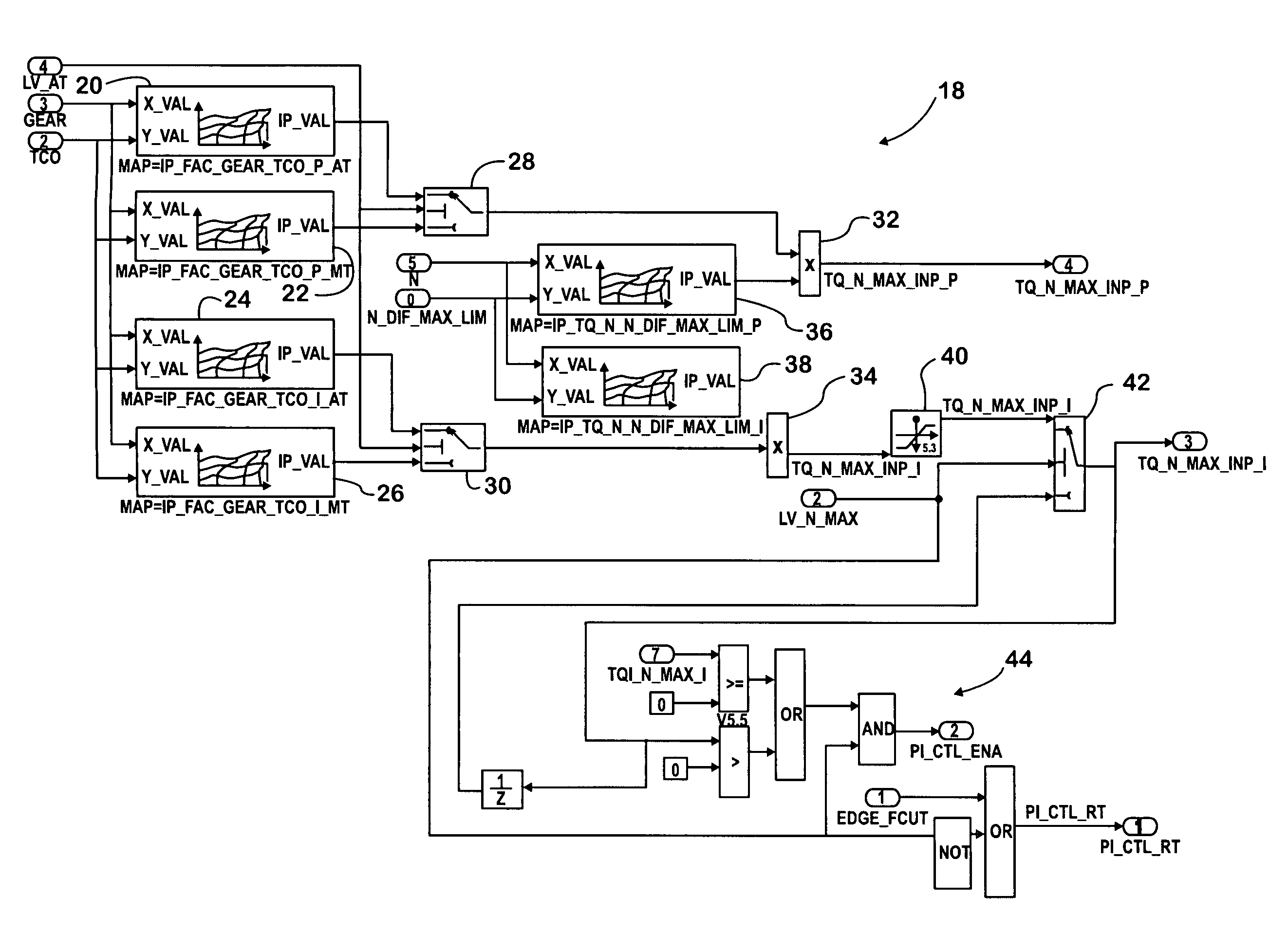
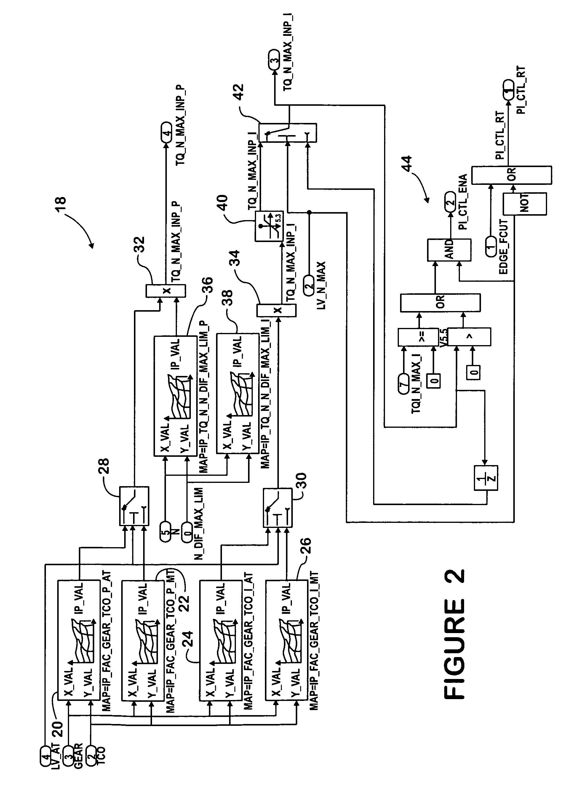
[0038]Engine controller 14 comprises the inventive engine speed control strategy 18 that is shown in FIG. 2.

[0039]FIG. 2 shows four two-dimensional maps 20, 22, 24, and 26. Each map is populated with values, each of which is correlated with a temperature data value representing engine...


PUM


Abstract

A PI control strategy controls engine speed to an engine speed set-point. A proportional map (36) is populated with data values to be used in calculating the P component of the strategy. An integral map (38) is populated with data values to be used in calculating the I component. Each data value in the maps is correlated with a speed data value representing engine speed (N) and a speed error data value representing the difference between engine speed and engine speed set-point (N_DIF_MAX_LIM). Values for proportional and integral components are selected from the respective maps by processing current engine speed data and current engine speed error data. The strategy uses the values from the maps for controlling engine speed to the speed set-point. Data values from other maps (20 and 24; or 22 and 26) modify the selected values from the proportional and integral maps (36, 38) for transmission type, transmission gear, and engine temperature.

Description

FIELD OF THE INVENTION[0001]This invention relates generally to internal combustion engines, especially compression ignition engines that propel large motor vehicles. More particularly it relates to an engine controller that has a PI (proportional / integral) control strategy for securing correspondence of engine speed to a speed set-point that at times may be engine high idle speed and at other times may be a request from a different controller to limit engine speed.BACKGROUND OF THE INVENTION[0002]A known electronic engine control system comprises a processor-based controller that processes data from various sources to develop control data for controlling certain aspects of engine operation such as speed and output torque. Control of speed and output torque of a diesel engine is in large part accomplished by controlling how the engine is fueled, but also in conjunction with control of other factors that include engine boost and back pressure, exhaust gas recirculation (EGR), and in ...

Claims


Application Information

Patent Timeline
IPC IPC(8): F02D31/00F02D41/08F02D41/10F02M3/08
CPCF02D31/007F02D41/2422F02D41/2451F02D2041/1409F02D2041/1422
Inventor WIESHUBER, PAUL A.BEAUCAIRE, JAMES T.MAJEWSKI, MICHAEL A.
Owner INT ENGINE INTPROP CO LLC
Learn More