Eureka AIR delivers breakthrough ideas for toughest innovation challenges, trusted by R&D personnel around the world.

Network supporting roaming, sleeping terminals

a network and terminal technology, applied in the field of radio data communication system improvement, can solve the problems of network and protocol problems, difficulty in maintaining the integrity of such multi-hop rf data communication system, and the number of base stations, so as to minimize collisions in the overlap region

Inactive Publication Date: 2009-05-19
AVAGO TECH WIRELESS IP SINGAPORE PTE +1
View PDF165 Cites 53 Cited by
  • Summary
  • Abstract
  • Description
  • Claims
  • Application Information

AI Technical Summary

Benefits of technology

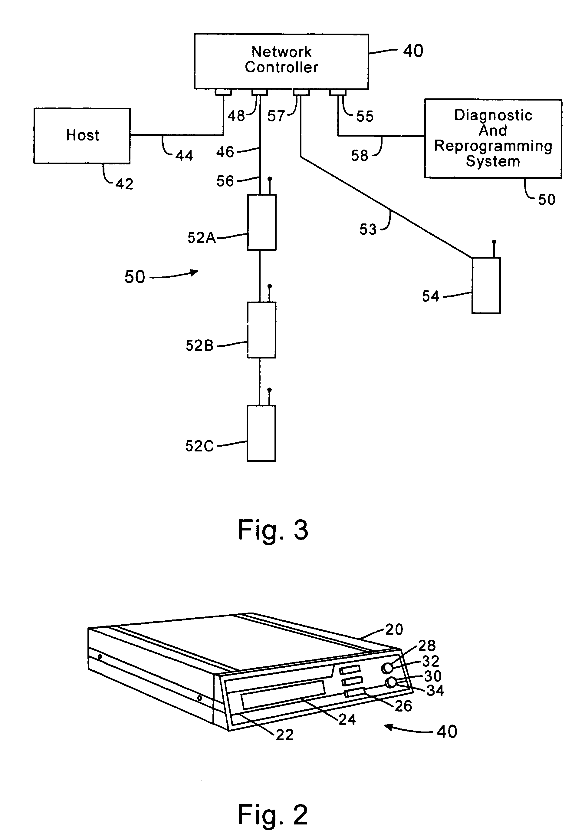
[0017]The third port of the invention, like the second port hereof, may be selectively configured to communicate by RS232, RS422, RS485 or NORAND® Radio One Node Network proprietary interface means. For both the second and third ports, as well as for the host port, configuration of the port is accomplished by selection of the port on the front panel of the invention controller with the select key and then selection of the desired interface configuration through appropriate use of the up and down keys to scroll to the correct means to be selected. Because the invention permits internal, software-controlled, selection of the desired interface means for each port, the end user may easily self configure the unit for a particular use, thereby providing a highly versatile device. In addition, the configuration choice means is simplified for the user, because the choices are conveniently displayed on the front panel display and a choice can be made from a scrollable list.
[0039]It is yet another object of the present invention to provide a communication protocol which minimizes collisions in the overlapping regions of different RF base stations.

Problems solved by technology

Additionally, depending upon the application and the operating conditions, a large number of base stations may be required to adequately serve the communication system.
Difficulties often arise in maintaining the integrity of such multiple-hop RF data communication systems.
However, when faced with hundreds of roaming terminals which move in and out of the range of multiple RF base stations, networking and protocol problems emerge.
To solve these problems, attempts have been made to decrease the number of base stations by increasing the base stations range; however, the range of the often battery-powered roaming terminals cannot match the increased range of the wall-socket-powered RF base stations.
Moreover, by increasing the range, collisions due to propagation times also increase, slowing down the overall communication time.
Although this solves the range problems associated with a single RF base station, additional problems result.
First, roaming terminals which are in an overlapping range region between RF base stations communicate with one base station but receive unwanted communication from the other.
Second, each roaming terminal often receives unwanted communication from other roaming terminals.
Third, each roaming terminal often transmits to a base station while that base station is receiving transmissions from another roaming terminal which is out of transmission range and therefore cannot be detected.
As a result, collisions in transmission result.
Additionally, as the number of RF base stations increase, communication pathways from the source to destination become more and more complex.
In an environment in which the spatial layout of the network continually changes, however, determining the most efficient pathways becomes very difficult.
This often leads to difficulty in detecting the fault and to long periods of down-time.

Method used


Image

  • Network supporting roaming, sleeping terminals
  • Network supporting roaming, sleeping terminals
  • Network supporting roaming, sleeping terminals

Examples


Embodiment Construction

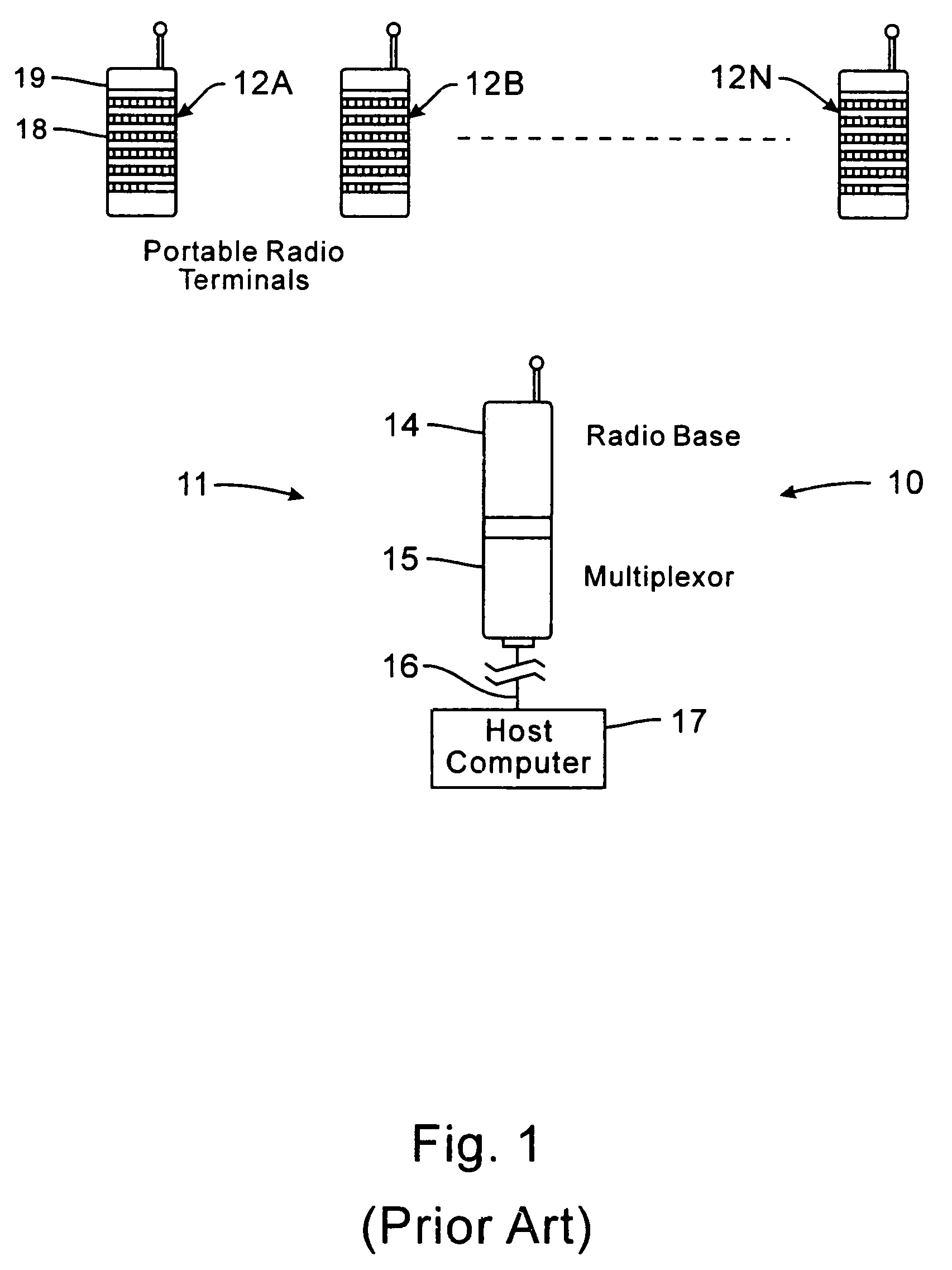
[0069]FIG. 1 shows an existing radio frequency data transmission system 10 wherein a base station transceiver means 11 has a number of mobile transceiver units such as 12A, 12B, . . . , 12N in radio communication therewith.

[0070]By way of example, the base station may be comprised of a radio base unit 14 such as the model RB3021 of Norand Corporation, Cedar Rapids, Iowa, which forms part of a product family known as the RT3210 system. In this case, the radio base 14 may receive data from the respective mobile RF terminals, e.g. of type RT3210, and transmit the received data via a network controller and a communications link 16 (e.g. utilizing an RS-232 format) to a host computer 17.

[0071]The data capture terminals 12A, 12B, . . . , 12N may each be provided with a keyboard such as 18, a display as at 19, and a bar code scanning capability, e.g., via an instant bar code reader such as shown in U.S. Pat. No. 4,766,300 issued Aug. 23, 1988, and known commercially as the 20 / 20 High Perfo...


PUM


Abstract

Improved apparatus for a radio communication system having a multiplicity of mobile transceiver units selectively in communication with a plurality of base transceiver units which, in turn, communicate with one or more host computers for storage and manipulation of data collected by bar code scanners or other collection means associated with the mobile transceiver units. A network controller and an adapter which has a simulcast and sequential mode provide selective interface between host computers and base transceivers. A scheme for routing data through the communication system is also disclosed wherein the intermediate base stations are organized into an optimal spanning-tree network to control the routing of data to and from the RF terminals and the host computer efficiently and dynamically. Additionally, redundant network and communication protocol is disclosed wherein the network utilizes a polling communication protocol which, under heavy loaded conditions, requires that a roaming terminal wishing to initiate communication must first determine that the channel is truly clear by listing for an entire interpoll gap time. In a further embodiment, a criterion used by the roaming terminals for attaching to a given base station reduces conflicts in the overlapping RF regions of adjacent base stations.

Description

CROSS-REFERENCE TO RELATED APPLICATIONS[0001]The present application is a continuation of application Ser. No. 09 / 318,668 filed May 25, 1999 which is a continuation of U.S. application Ser. No. 08 / 545,108, filed Oct. 19, 1995, now U.S. Pat. No. 5,940,771, which is a continuation of: 1) U.S. application Ser. No. 07 / 947,102, filed Sep. 14, 1992, now abandoned; and 2) U.S. application Ser. No. 07 / 907,927, filed Jun. 30, 1992, now abandoned. application Ser. No. 07 / 947,102 is also a continuation in part of application Ser. No. 07 / 907,927 which is a continuation in part of: 1) U.S. application Ser. No. 07 / 857,603, filed Mar. 30, 1992, now abandoned, which is a continuation in part of U.S. application Ser. No. 07 / 700,704, filed May 14, 1991, now abandoned, which is itself a continuation in part of U.S. application Ser. No. 07 / 699,818, filed May 13, 1991, now abandoned; 2) PCT Application No. US92 / 03982, filed May 13, 1992, now abandoned; 3) U.S. application Ser. No. 07 / 769,425, filed Oct....

Claims


Application Information

Patent Timeline
Patent Type & Authority Patents(United States)
IPC IPC(8): H04W52/44H04W52/28G08C17/02H01Q1/00H04B1/16H04B7/005H04B17/00H04L1/00H04L12/28H04L12/403H04L12/56H04L29/06H04M1/73H04W40/22H04W40/24H04W40/30H04W40/36H04W52/34
CPCG08C17/02H01Q1/007H04L1/0003H04L1/0025H04L1/0032H04L45/00H04W52/0225H04W52/343H04B17/318H04B17/0085H04W40/02H04W40/22H04W40/246H04W40/248H04W40/30H04W40/36H04W52/029H04L69/18H04L69/14Y02B60/50G08C2201/20Y02D30/70
Inventor GOLLNICK, CHARLES D.LUSE, RONALD E.PAVEK, JOHN G.SOJKA, MARVIN L.CNOSSEN, JAMES D.DANIELSON, ARVIN D.MAHANY, RONALD L.DETWEILER, MARY L.SPIESS, GARY N.WEST, GUY J.YOUNG, AMOS D.MEIER, ROBERT C.CARGIN, JR., KEITH K.ARENSDORF, RICHARD C.GEERS, ROBERT G.
Owner AVAGO TECH WIRELESS IP SINGAPORE PTE
Why Eureka
Eureka Blog
Learn More