Device for locking an electrical device to an accessory part

a technology for locking electrical devices and accessories, which is applied in the direction of rod connections, cell components, couplings, etc., can solve the problems of property damage or injury, and the two-stage locking mechanism is unable to reliably prevent the battery pack from falling ou

Active Publication Date: 2009-05-19
ROBERT BOSCH GMBH
View PDF10 Cites 11 Cited by
  • Summary
  • Abstract
  • Description
  • Claims
  • Application Information

AI Technical Summary

Benefits of technology

[0008]Accordingly, it is an object of the present invention to provide a device for locking an electrical device to an accessory part, which avoids the disadvantages of the prior art.
[0010]When the device for locking an electrical device to an accessory part is designed in accordance with the present invention, it has the advantage over the prior art that in locking mechanisms with either a one-stage or a two-stage locking action, the battery pack can be prevented from uncontrollably dropping out of the guide if the user is not holding it or is not holding it correctly when the guide is tilted downward and the release mechanism is intentionally or unintentionally actuated.
[0012]Since battery packs are usually removed while power tools are being held in their normal operating position in which the battery pack is pointing downward, the force acting on the accessory part can easily be exerted by the weight of the battery pack if its center of gravity is lower in the safety position than during its movement along the guide and gravity consequently pulls the battery pack downward into the safety position. But since this orientation is not necessarily always maintained and could also be different in other electrical devices, in a preferred embodiment of the present invention, the force acting on the accessory part is a spring force that pushes or pulls the accessory part into the safety position and has the advantage over gravity that it works regardless of the spatial orientation of the components.
[0013]In another preferred embodiment of the present invention, the spring acts on the accessory part essentially transversely to the movement direction of the accessory part in the guide in order to move the accessory part directly and without deflection of the force direction, into the safety position, in a direction transverse to its movement path in the guide. Even when a spring is used to generate the force required, it is preferable for the safety position to be offset downward in relation to the movement path of the battery pack in the guide in order to provide a redundancy by means of the battery pack's weight acting on it in the same direction as the force of the spring during the movement of the battery pack into the safety position.
[0015]According to another preferred embodiment of the present invention, the electrical device and the accessory part are adapted to each other so that in the safety position, the accessory part is in fact prevented from moving toward the removal position, but is able to freely move in the opposite direction toward the locking position so that when being attached to the electrical device, the accessory part can be moved freely all the way into the locking position, even if it is moved into the safety position in the meantime because the user is not holding it correctly. This is preferably achieved by means of the fact that the accessory part and the electrical device are provided with cooperating stop surfaces at one end and are provided with cooperating leading bevels at the other; in the safety position, the stop surfaces are situated opposite one another in the removal direction and prevent the accessory part from being moved further toward the removal position, while the leading bevels are situated opposite from one another in the locking direction and cause the accessory part to be automatically pushed back out of the safety position when the force acting on it has moved it into the safety position while it is being slid into the locking position.

Problems solved by technology

This can result in the battery pack slipping out of the guide during transport or operation of the power tool when the latter is tilted downward toward the removal position, which can lead to property damage or injury.
But if the user does not hold the battery pack while actuating the release mechanism and the guide is simultaneously pointing obliquely downward from the locking position, then even a two-stage locking mechanism is unable to reliably prevent the battery pack from falling out.

Method used


Image

  • Device for locking an electrical device to an accessory part
  • Device for locking an electrical device to an accessory part
  • Device for locking an electrical device to an accessory part

Examples


Embodiment Construction

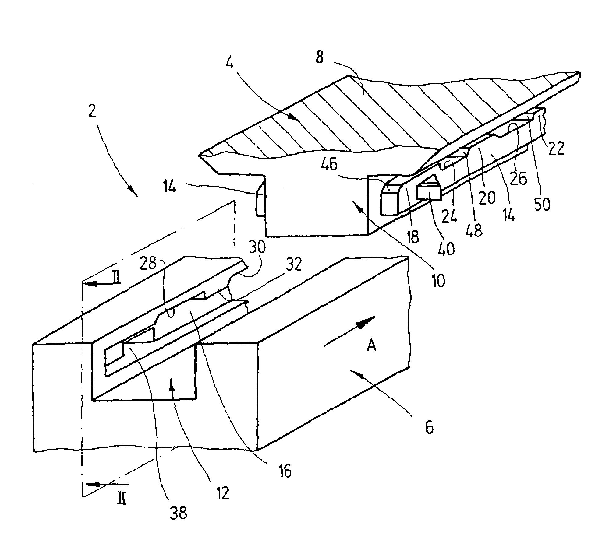
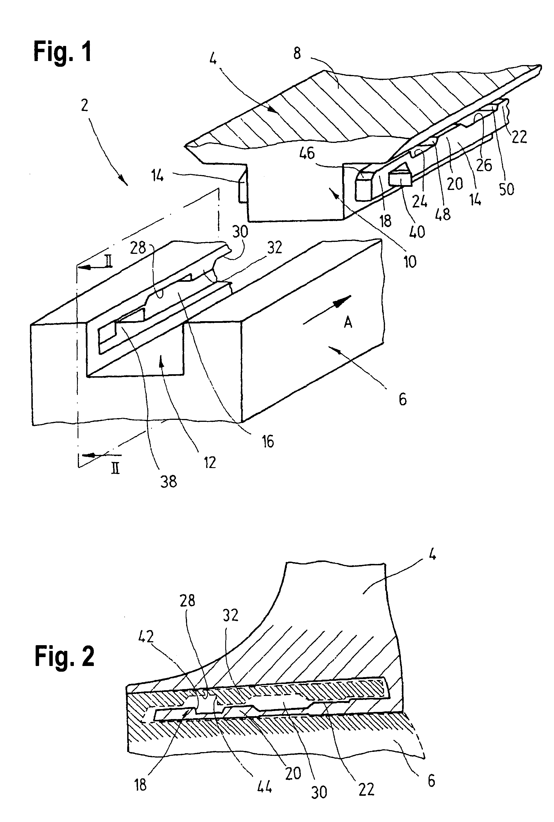
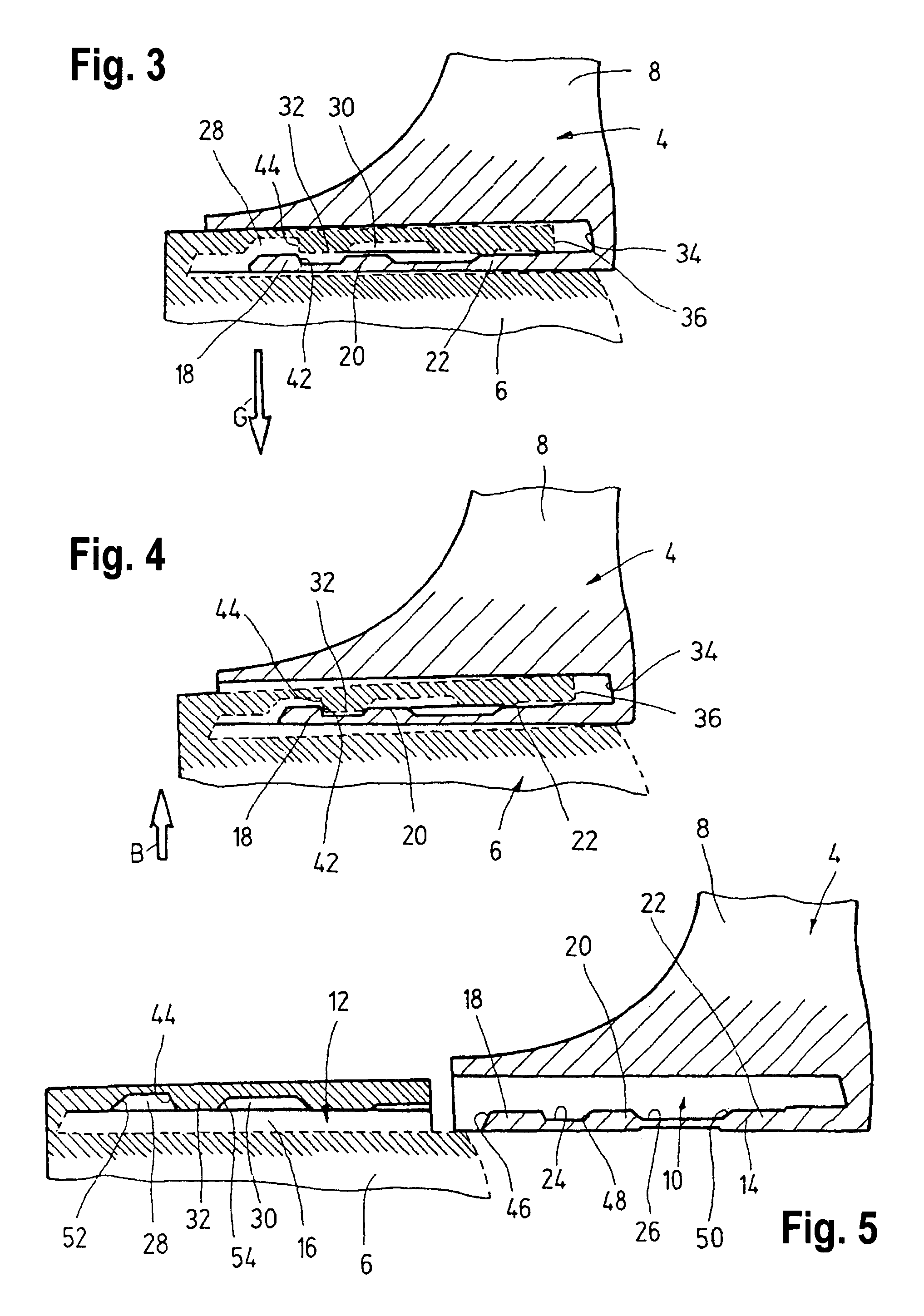
[0027]The locking devices 2 shown in the drawings are used to lock a cordless power tool 4, for example a hand-guided percussion drill, to a battery pack 6 required to supply power to the power tool 4.

[0028]As best shown in FIGS. 1 through 5, on the free lower end of its handle 8, the power tool 4 is provided in a known fashion with a protruding guide rail 10 that can be slid in the direction of the arrow A into a guide groove 12 let into the upper end of the battery pack 6. This guide groove 12 has a cross section complementary to the cross section of the guide rail 10 and, together with it, constitutes a linear guide that defines the predetermined insertion direction (arrow A).

[0029]The guide rail 10 is provided with two laterally protruding guide strips 14, whose cross sections essentially correspond to the cross sections of two guide slots 16 (only one of which is visible in FIG. 1) situated opposite from each other inside the guide groove 12. The tops of the two guide strips 14...


PUM

PropertyMeasurementUnit
forceaaaaaaaaaa
weightaaaaaaaaaa
movementaaaaaaaaaa

Abstract

A device for locking, an electrical device to an accessory part has a guide configured to guide the accessory part in a predetermined movement direction as it moves between a locking position in which it is locked the electrical device and a removal position in which it is removed from the electrical device, the guide having a break in at least one location between the locking position and removal position, and at the location a force acting on the accessory part moves the accessory part into a safety position in which the accessory part is prevented from moving further along the guide into the removal position.

Description

CROSS-REFERENCE[0001]The invention described and claimed hereinbelow is also described in DE 102004044331.9, filed Sep. 9, 2004. This German Patent Application, whose subject matter is incorporated here by reference, provides the basis for a claim of priority of invention under 35 U.S.C. 119 (a)-(d).BACKGROUND OF THE INVENTION[0002]The present invention relates to a device for locking an electrical device to an accessory part.[0003]Locking devices of this type are used, for example, to reliably connect cordless hand-guided power tools to a battery pack used as a power supply.[0004]The known locking devices usually have a linear guide provided on the power tool into which the battery pack is slid until, after being slid all the way in, it comes into contact with a stop and is locked in this position in relation to the power tool, while simultaneously producing an electrical connection between a battery of the battery pack and an electrical circuit of a consumer of the power tool. The...

Claims


Application Information

Patent Timeline
Patent Type & Authority Patents(United States)
IPC IPC(8): F16B21/08B25F5/02H01M50/204H01M50/244H01M50/247H01M50/262
CPCB25F5/02H01M2/1022Y10T403/59Y10T403/32442Y10T403/591Y10T403/32451Y10T403/604Y10T403/599Y10T403/61Y10T403/60Y02E60/10H01M50/204
Inventor REJMAN, MARCINMATTHIAS, WOLF
Owner ROBERT BOSCH GMBH
Why Eureka
Try Eureka