Plasma display module

a technology of plasma display module and display plate, which is applied in the direction of discharge tube main electrodes, casings/cabinets/drawers details, lighting and heating apparatus, etc., can solve the problems of increasing the total production cost of the plasma display module, increasing the number of processes and components, and increasing the heat generation. , to achieve the effect of improving the heat dissipation structure, reducing the number of processes and components, and being easy to mak

Inactive Publication Date: 2009-05-12
SAMSUNG SDI CO LTD
View PDF36 Cites 23 Cited by
  • Summary
  • Abstract
  • Description
  • Claims
  • Application Information

AI Technical Summary

Benefits of technology

[0010]It is also an object of the present invention to provide a plasma display module with an improved heat dissipation structure.
[0011]It is further an object of the present invention to provide a plasma display module that is easy to make.
[0012]It is still an object of the present invention to provide a plasma display module which can remarkably reduce the number of processes and the number of components and reduce total production cost without deteriorating heat dissipating efficiency by fabricating a wave-type heat dissipating plate integrally attached to a cover plate.
[0013]It is also an object of the present invention to provide a plasma display module having a reduced weight by reducing a weight and a size of a heat dissipating plate.

Problems solved by technology

When the plasma display module is driven, a large amount of heat is generated by the integrated circuit chip mounted on the signal transmitting unit.
However, because of limitations in the current extrusion molding technology, the such a flat heat dissipating plate must be fabricated as an extrusion material that is separate from the cover plate and then be attached to the cover plate.
Accordingly, the number of processes and the number of components increase while the total production cost of the plasma display module increases.

Method used


Image

  • Plasma display module
  • Plasma display module
  • Plasma display module

Examples


Embodiment Construction

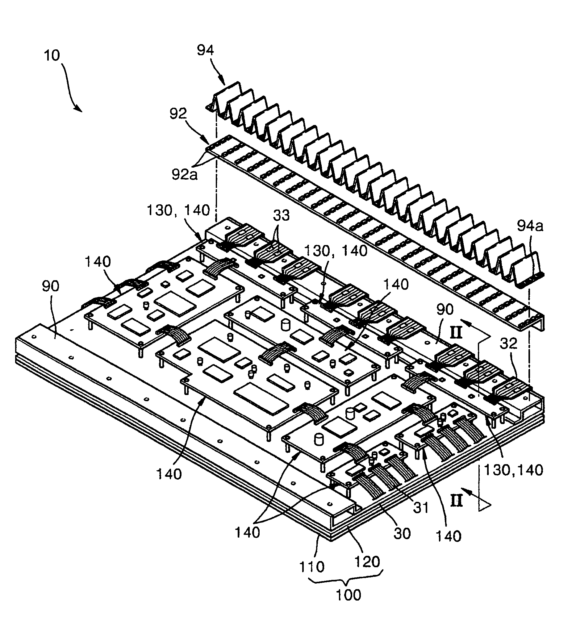
[0025]Turning now to the figures, FIG. 1 is a partial exploded perspective view of a plasma display module 10 according to an embodiment of the present invention, FIG. 2 is a partial cross-sectional view of the plasma display module 10 taken along line II-II of FIG. 1, FIG. 3 is a partial exploded perspective view of a cover plate 92 and a heat dissipating plate 94 of the plasma display module 10 of FIG. 1, and FIG. 4 is a partial exploded perspective view of a plasma display panel 100 of the plasma display module 10 of FIG. 1. Referring the figures, a plasma display module 10 according the present embodiment includes a plasma display panel 100. For the present invention, any one of various kinds of plasma display panels can be employed. For example, a three-electrode AC surface discharge plasma display panel can be employed.

[0026]Turning now to FIG. 4, FIG. 4 illustrates the case where the plasma display panel 100 of FIG. 1 is a three-electrode AC surface discharge plasma display p...


PUM


Abstract

A plasma display module including a plasma display panel adapted to display an image with gas discharge, a chassis adapted to support the plasma display panel, a driving unit arranged on the chassis and adapted to generate an electrical signal that drives the plasma display panel, an integrated circuit chip arranged on a signal transmitting unit, the integrated circuit chip being adapted to control electrical signal transfer between the driving unit and the plasma display panel, a cover plate arranged on the signal transmitting unit and adapted to cover the integrated circuit chip and a wave-type heat dissipating plate arranged on the cover plate.

Description

CLAIM OF PRIORITY[0001]This application makes reference to, incorporates the same herein, and claims all benefits accruing under 35 U.S.C. § 119 from an application for PLASMA DISPLAY MODULE earlier filed in the Korean Intellectual Property Office on 6 Apr. 2005 and there duly assigned Serial No. 10-2005-0028553.BACKGROUND OF THE INVENTION[0002]1. Field of the Invention[0003]The present invention relates to a plasma display module, and more particularly, to a plasma display module having improved heat dissipating efficiency.[0004]2. Description of the Related Art[0005]A plasma display module is a display module that displays an image using a gas discharge phenomenon. Recently, the plasma display module is attracting much attention because it provides a wide viewing angle, is slim, has a high quality image, has a large area, and so on.[0006]The plasma display panel includes a first panel and a second panel. The plasma display module includes a signal transmitting unit that is dispose...

Claims


Application Information

Patent Timeline
Patent Type & Authority Patents(United States)
IPC IPC(8): H05K7/20
CPCH05K5/02H05K7/20963E04G11/085
Inventor JEONG, KWANG-JIN
Owner SAMSUNG SDI CO LTD
Why Eureka
Try Eureka