
Illumination system to eliminate laser speckle and projection system employing the same

a laser speckle and projection system technology, applied in the field of illumination systems, can solve the problems of complex manufacturing of optical fiber bundles with different lengths, degraded speckle removal efficiency, and inability to effectively reduce or eliminate laser speckl

Inactive Publication Date: 2009-05-05
SAMSUNG ELECTRONICS CO LTD
View PDF21 Cites 28 Cited by
  • Summary
  • Abstract
  • Description
  • Claims
  • Application Information

AI Technical Summary

Benefits of technology

The present invention provides an illumination system and a projection system that can effectively reduce or eliminate laser speckle by spatially averaging a laser beam using a diffractive optical element or temporally averaging the laser beam using a reflective vibrator. The systems include an optical fiber bundle to divide the laser beam into multiple sub-beams, which can be shaped using a beam-shaping unit and a vibrator to temporally average the sub-beams. The systems also include a display device to produce an image using the sub-beams. The technical effects of the invention include reducing speckle in laser beams, improving image quality, and reducing the size of the illumination and projection systems.

Problems solved by technology

However, the laser-based projection system suffers from speckle due to a coherence of a laser beam.
The speckle results from interference among randomly phased coherent beams reflected from a rough surface.
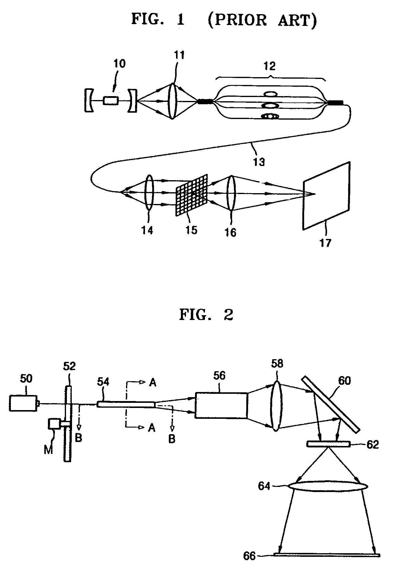
However, since the beams passing through the optical fiber bundle 12 have different phases, the efficiency of speckle removal is degraded.
Furthermore, the optical fiber bundle 12 having the optical fibers with different lengths is complicated to manufacture.

Method used


Image

  • Illumination system to eliminate laser speckle and projection system employing the same
  • Illumination system to eliminate laser speckle and projection system employing the same
  • Illumination system to eliminate laser speckle and projection system employing the same

Examples


Embodiment Construction

[0033]Reference will now be made in detail to the embodiments of the present general inventive concept, examples of which are illustrated in the accompanying drawings, wherein like reference numerals refer to the like elements throughout. The embodiments are described below in order to explain the present general inventive concept while referring to the figures.

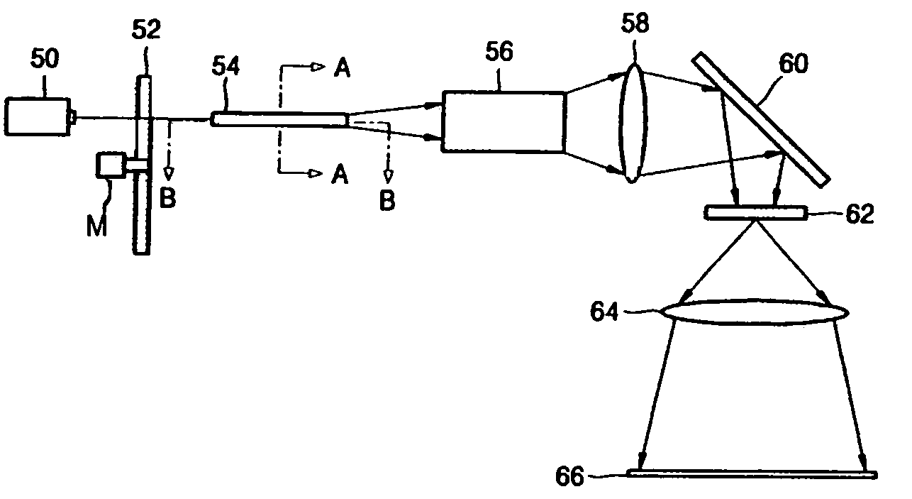
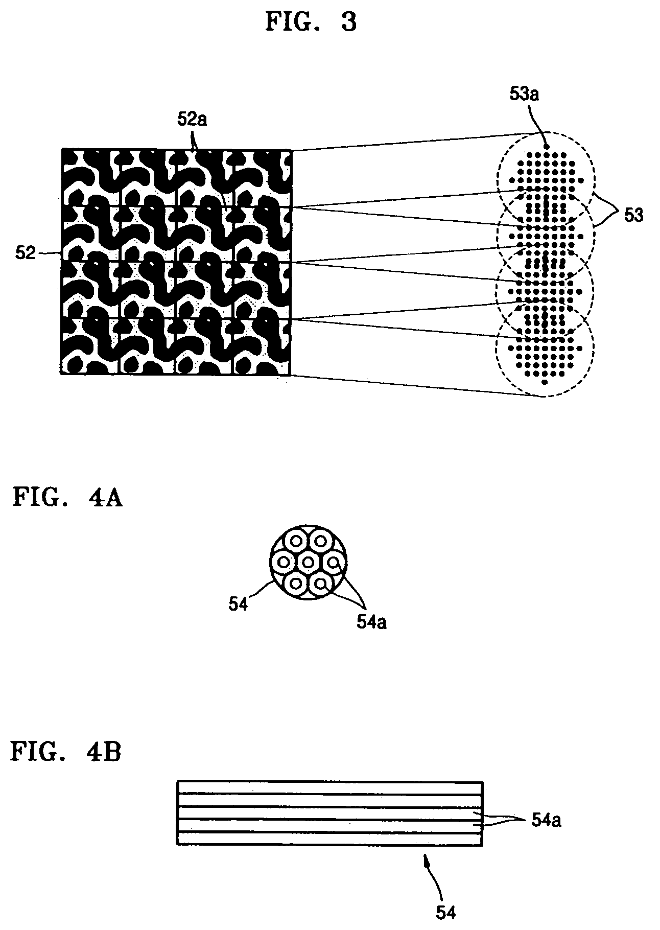
[0034]FIG. 2 illustrates a projection system to eliminate laser speckle according to an embodiment of the present general inventive concept. Referring to FIG. 2, the projection system includes a laser light source 50, a diffractive optical element (DOE) 52 to remove the speckle of a laser beam emitted by the laser light source 50, an optical fiber bundle 54 to divide the laser beam passing through the DOE 52 into sub-beams, a beam-shaping unit 56 to shape the sub-beams, and a display device 62 to produce an image from the sub-beams shaped by the shaping unit 56.

[0035]The projection system can further include a condensing lens...


PUM


Abstract

An illumination system designed to remove laser speckle and a projection system including the same. The illumination system includes a laser light source having at least one laser, a diffractive optical element to divide a laser beam emitted from the laser light source into a plurality of sub-beams and to periodically move in such a way as to temporally average the speckle of the laser beam, and an optical fiber bundle including a plurality of fibers with the same length to divide the sub-beams into smaller sub-beams. The illumination system divides the laser beam emitted from the laser light source into sub-beams and temporally or spatially averages the sub-beams, thereby effectively reducing or removing laser speckle. The projection system employing the illumination system can provide improved image quality.

Description

CROSS-REFERENCE TO RELATED APPLICATIONS[0001]This application claims the benefit under 35 U.S.C. § 119 of Korean Patent Application No. 10-2004-106536, filed on Dec. 15, 2004, in the Korean Intellectual Property Office, the disclosure of which is incorporated herein in its entirety by reference.BACKGROUND OF THE INVENTION[0002]1. Field of the Invention[0003]The present general inventive concept relates to an illuminating system designed to eliminate speckle produced by laser light and a projection system employing the same, and more particularly, to an illumination system designed to effectively reduce or eliminate laser speckle by dividing a beam emitted from a laser light source into sub-beams and temporally or spatially averaging the sub-beams and a projection system employing the same.[0004]2. Description of the Related Art[0005]A projection system using a laser light source provides a wide range of color rendition due to a wide color gamut while achieving high optical efficienc...

Claims


Application Information

Patent Timeline
Patent Type & Authority Patents(United States)
IPC IPC(8): G03B21/14
CPCG02B5/1866G02B27/0944G02B27/0994G02B27/48G03B21/00H04N9/3152H04N9/3161H04N9/3197G02B5/32G03H2227/03G03B21/005H01S3/005G02B26/0858
Inventor KIM, SUNG-HADHO, SANG-WHOE
Owner SAMSUNG ELECTRONICS CO LTD
Learn More