
Method and apparatus for producing a signature for an object

a technology of object signature and object type, applied in the field of estimating similarity between complex objects, can solve the problems of unrealistic keeping all data objects in the main memory, drawback of charikar's model,

Inactive Publication Date: 2009-04-21
GOOGLE LLC
View PDF0 Cites 8 Cited by
  • Summary
  • Abstract
  • Description
  • Claims
  • Application Information

AI Technical Summary

Benefits of technology

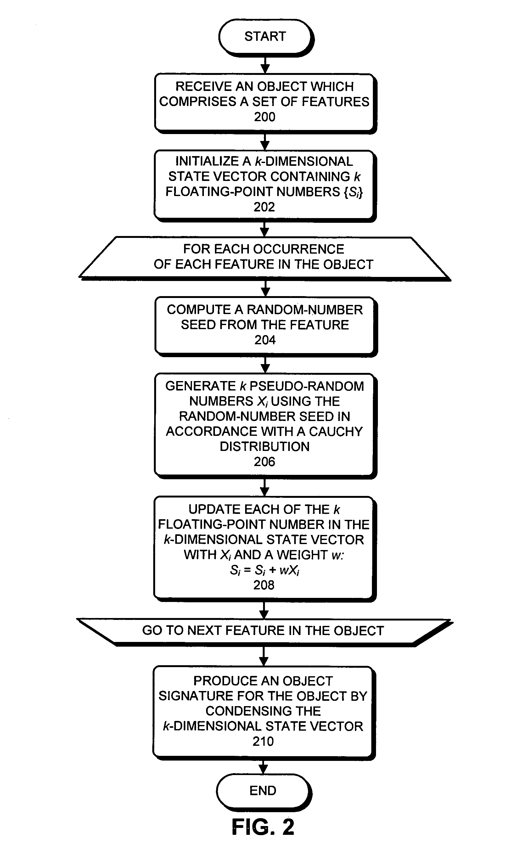
[0009]One embodiment of the present invention provides a system that produces an object signature for an object, wherein the object comprises a set of features. During operation, the system first initializes a k-dimensional state vector {s1, s2, . . . , sk} containing floating-point numbers. Next, for each occurrence of each feature in the object, the system (1) computes a random-number seed from the feature; (2) generates k pseudo-random floating-point numbers {X1, X2, . . . , Xk} using the random-number seed, wherein each Xi(iε[1, k]) is generated in accordance with an α-stable distribution, wherein 1≦α<2; and (3) updates each floating-point number si in the k-dimensional state vector using an associated pseudo-random floating-point number Xi. The system then produces the object signature for the object by condensing the k-dimensional state vector. Note that using an α-stable distribution with 1≦α<2 to generate the k pseudo-random floating-point numbers for each feature reduces the influence of multiple occurrences of a given feature on the object signature.

Problems solved by technology

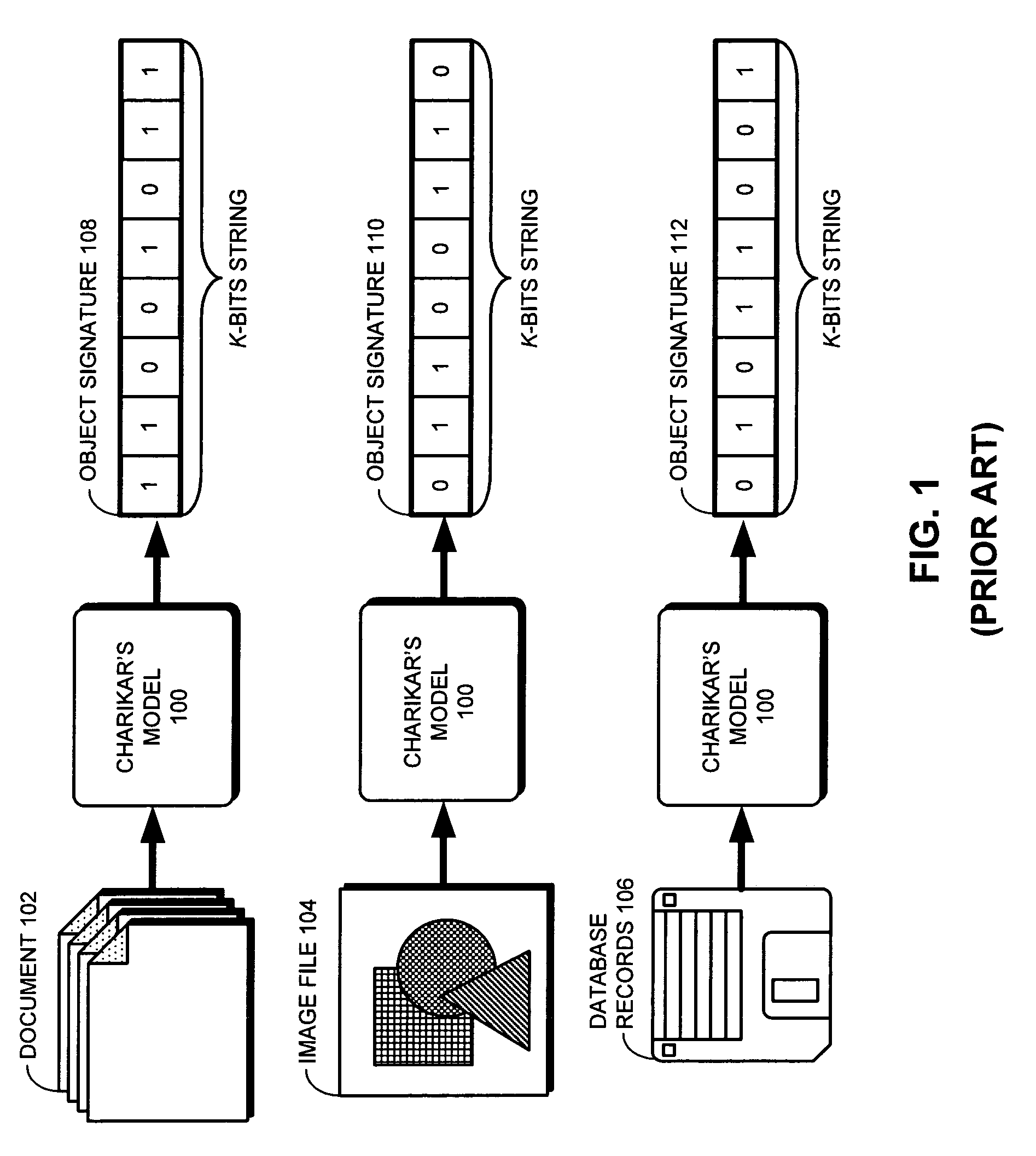
However, it is unrealistic to keep all of the data objects in the main memory when applications are dealing with large numbers of “massive” data objects, such as data objects from a genome database, multimedia files, or web page repositories.
Unfortunately, Charikar's model has a drawback.

Method used


Image

  • Method and apparatus for producing a signature for an object
  • Method and apparatus for producing a signature for an object
  • Method and apparatus for producing a signature for an object

Examples


Embodiment Construction

[0023]The following description is presented to enable any person skilled in the art to make and use the invention, and is provided in the context of a particular application and its requirements. Various modifications to the disclosed embodiments will be readily apparent to those skilled in the art, and the general principles defined herein may be applied to other embodiments and applications without departing from the spirit and scope of the present invention. Thus, the present invention is not limited to the embodiments shown, but is to be accorded the widest scope consistent with the principles and features disclosed herein.

[0024]The data structures and code described in this detailed description are typically stored on a computer-readable storage medium, which may be any device or medium that can store code and / or data for use by a computer system. This includes, but is not limited to, magnetic and optical storage devices such as disk drives, magnetic tape, CDs (compact discs) ...


PUM


Abstract

One embodiment of the present invention provides a system that produces an object signature for an object, wherein the object comprises a set of features. During operation, the system first initializes a k-dimensional state vector {s1, s2, . . . , sk}containing floating-point numbers. Next, for each occurrence of each feature in the object, the system (1) computes a random-number seed from the feature; (2) generates k pseudo-random floating-point numbers {X1, X2, . . . , Xk} using the random-number seed, wherein each Xi(iε[1, k]) is generated in accordance with an α-stable distribution, wherein 1≦α<2; and (3) updates each floating-point number si in the k-dimensional state vector using an associated pseudo-random floating-point number Xi. The system then produces the object signature for the object by condensing the k-dimensional state vector. Note that using an α-stable distribution with 1≦α<2 to generate the k pseudo-random floating-point numbers for each feature reduces the influence of multiple occurrences of a given feature on the object signature.

Description

BACKGROUND[0001]1. Field of the Invention[0002]The present invention relates to techniques for estimating similarity between complex objects. More specifically, the present invention relates to a method and an apparatus that estimates similarity between complex objects by comparing object signatures for the complex objects.[0003]2. Related Art[0004]Data explosion in the information age is demanding an increasing number of computing applications to routinely process huge amounts of input data. For example, search engines on the Internet must comb through the billions of web pages that are presently accessible through the Internet and obtain relevant results within a fraction of a second. Traditionally, the computational approaches used by these applications assume that entire data objects can be stored in main memory while the data objects are being processed. However, it is unrealistic to keep all of the data objects in the main memory when applications are dealing with large number...

Claims


Application Information

Patent Timeline
IPC IPC(8): G06F17/00G06N5/00
CPCH04L9/0643H04L9/0662H04L9/0891H04L9/14G11B20/00181
Inventor ENGEBRETSEN, LARS
Owner GOOGLE LLC
Learn More