Optical signal regenerative repeater, optical gate control method, and optical signal regeneration method
a repeater and optical signal technology, applied in electromagnetic repeaters, distortion/dispersion elimination, fibre transmission, etc., can solve the problems of timing jitter tolerance, distortion of the regenerated output waveform, signal deterioration, etc., and achieve the effect of large pulse time width
- Summary
- Abstract
- Description
- Claims
- Application Information
AI Technical Summary
Benefits of technology
Problems solved by technology
Method used
Image

Examples
first embodiment
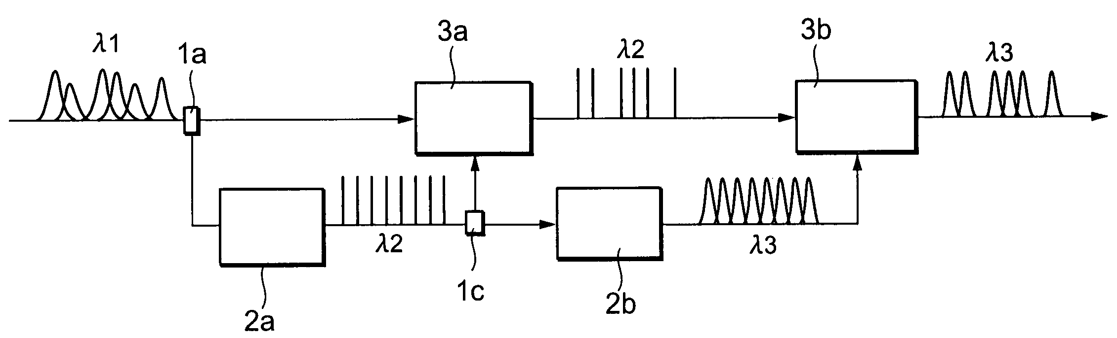
[0066]FIG. 9 shows a schematic configuration of an optical signal regenerative repeater according to a first embodiment of the present invention. This optical signal regenerative repeater comprises a series connection between a first optical 3R repeater and a second optical 3R repeater. The first optical 3R repeater includes an optical branching device 1a, a clock extraction unit 2a and an optical gate 3a, the second optical 3R repeater includes an optical branching device 1b, a clock extraction unit 2b and an optical gate 3b. The processes using the above described 3R functions are sequentially performed twice for a deteriorated optical communication signal pulse (wavelength λ 1) having a large pulse time width. The optical gates 3a and 3b are fast optical gates, such as the above described push-pull optical gates (e.g., SMZ optical gates, polarization discriminating SMZ optical gates, or nonlinear optical loop mirrors).
[0067]In the first optical 3R repeater, an input optical commu...
second embodiment
[0091]In the first embodiment, the clock extraction unit 2b of the second optical 3R repeater extracts a clock from the intermediate signal light that is output at the optical gate 3a of the first optical 3R repeater. However, a clock may be extracted from a optical clock pulse generated by the clock extraction unit 2a (diversion of a clock). An explanation will now be given for a second embodiment for which such a clock diversion is adopted.
[0092]FIG. 12 is a schematic block diagram showing the configuration of an optical light regenerative repeater according to a second embodiment of the present invention. This optical signal regenerative repeater has the same configuration as that in FIG. 9 for the first embodiment, except that a optical clock pulse output by a clock extraction unit 2a is divided into two by an optical branching device 1c, and that one of the obtained optical clock pulses is supplied as controlled light to an optical gate 3a while the other is supplied to a clock...
third embodiment
[0094]A wavelength converter and a pulse width converter can be employed instead of the clock extraction unit 2b in the second optical 3R repeater according to the second embodiment. An explanation will now be given for an optical signal regenerative repeater that adopts such a configuration.
[0095]FIG. 13 is a schematic block diagram showing the configuration of an optical signal regenerative repeater according to a third embodiment of the present invention. This optical signal regenerative repeater is so designed that in the configuration in FIG. 9 the clock extraction unit 2b is replaced with a wavelength converter 20 and a pulse width converter 21. The same reference numerals are provided for the corresponding components in FIG. 13.
[0096]A optical clock pulse (wavelength λ 2) output by a clock extraction unit 2a is divided into two by an optical branching device 1c, and one of the obtained optical clock pulses is supplied as controlled light to an optical gate 3a, while the other...
PUM
 Abstract
Description
Claims
Application Information
 - R&D
- Intellectual Property
- Life Sciences
- Materials
- Tech Scout
- Unparalleled Data Quality
- Higher Quality Content
- 60% Fewer Hallucinations
Browse by: Latest US Patents, China's latest patents, Technical Efficacy Thesaurus, Application Domain, Technology Topic, Popular Technical Reports.
© 2025 PatSnap. All rights reserved.Legal|Privacy policy|Modern Slavery Act Transparency Statement|Sitemap|About US| Contact US: help@patsnap.com