
Air separation membrane module with variable sweep stream

a technology of air separation membrane and sweep stream, which is applied in the direction of membranes, auxillary pretreatment, separation processes, etc., can solve the problems of optimum performance of gas-separation membrane modules and sweep stream that would not justify the effor

Active Publication Date: 2009-04-14
GENERON IGS
View PDF14 Cites 47 Cited by
  • Summary
  • Abstract
  • Description
  • Claims
  • Application Information

AI Technical Summary

Benefits of technology

[0053]The following Examples illustrate the benefits of the present invention. These Examples provide the results of a computer simulation showing the effect of the invention, as used in an aircraft during various phases of flight. In these Examples, the module is assumed to be a counter-current, bore-side fed structure, having a diameter of six inches and a length of 36 inches. The module is assumed to contain 500,000 fibers with an oxygen permeance of 15×1010−5 cm3 / cm2 cm hg sec, and an oxygen / nitrogen selectivity of 7.8. The fiber size was chosen to be 135×95 microns. The sweep stream was assumed to sweep uniformly those regions on the shell side of the module that had over 21% oxygen in the non-sweep simulations.
, as used in an aircraft during various phases of flight. In these Examples, the module is assumed to be a counter-current, bore-side fed structure, having a diameter of six inches and a length of 36 inches. The module is assumed to contain 500,000 fibers with an oxygen permeance of 15×1010−5 cm3 / cm2 cm hg sec, and an oxygen / nitrogen selectivity of 7.8. The fiber size was chosen to be 135×95 microns. The sweep stream was assumed to sweep uniformly those regions on the shell side of the module that had over 21% oxygen in the non-sweep simulations.

Problems solved by technology

The following practical considerations may prevent optimum performance of a gas-separation membrane module.
In many cases, however, the advantage that might be obtained by adjusting the sweep stream would not justify the effort.

Method used


Image

  • Air separation membrane module with variable sweep stream
  • Air separation membrane module with variable sweep stream
  • Air separation membrane module with variable sweep stream

Examples


example 1

[0054]This Example simulates the take-off or landing phase, i.e. when the aircraft is at a low elevation. The pressure is assumed to be 45 psig. The simulation was run so as to generate a product (retentate) gas having oxygen concentrations of 12%, 7%, and 5%. This range is a typical one for inerting of fuel tanks. Even when the oxygen concentration is as high as 12%, an explosion of the fuel tank is unlikely.

[0055]The simulation was operated first without simulating any sweep stream. The results are as follows:

[0056]

Oxygen ConcentrationProductBleed Airin Product GasFlowRequired12% 378 scfh527 scfh7%187 scfh330 scfh5%141 scfh280 scfh

[0057]The “bleed air” is the feed gas, which is taken from the high-pressure ambient air produced by the turbines. The feed gas is what is directed through the bores of the fibers, to produce an oxygen-depleted retentate gas. The table shows the required flow rates of bleed air to produce the indicated rates of product flow, for each concentration of oxy...

example 2

[0063]This Example was designed to investigate a climb or descent, wherein an aircraft climbs from sea level to 35,000 feet, or descends from that altitude to sea level. For simplicity, an intermediate elevation of about 15,000 feet was chosen, where the bleed air pressure is assumed to be 53 psia and the permeate exits the module at about 8.5 psia.

[0064]The following tables show the results of the simulation. The module was assumed to be the same as in Example 1.

[0065]The following table shows the product flow and bleed air requirement for a module in which there is no sweep gas:

[0066]

Oxygen ConcentrationProductBleed Airin Product GasFlowRequired12% 439 scfh589 scfh7%217 scfh359 scfh5%163 scfh300 scfh

[0067]The following table shows the product flow and bleed air requirements where the module is swept with low-pressure, ambient air (21% oxygen).

[0068]

Product OxygenProductBleed Air% of ShellLow PressureConc.FlowRequiredSide SweptSweep Flow12% 677 scfh850 scfh100%750 scfh7%288 scfh440...

example 3

[0071]This Example investigates the case of high-altitude cruise. The aircraft is assumed to be at about 35,000 feet. The bleed air pressure is assumed to have dropped to about 45 psia, and the permeate will exit the module at about 3 psia. The module may be operated at fairly low oxygen concentration, less than about 7%, during this portion of the flight, so as to inert the fuel tanks sufficiently to compensate for an influx of ambient air (21% oxygen) when the aircraft begins to descend. The details of the module are the same as in the previous Examples.

[0072]The following table shows the product flow and bleed air requirement for a module in which there is no sweep gas:

[0073]

Oxygen ConcentrationProductBleed Airin Product GasFlowRequired12% 575 scfh730 scfh7%287 scfh432 scfh5%216 scfh356 scfh2%126 scfh256 scfh

[0074]The following table shows the product flow and bleed air requirements where the module is swept with low-pressure, ambient air (21% oxygen).

[0075]

Product OxygenProductB...


PUM

PropertyMeasurementUnit
angleaaaaaaaaaa
angleaaaaaaaaaa
angleaaaaaaaaaa

Abstract

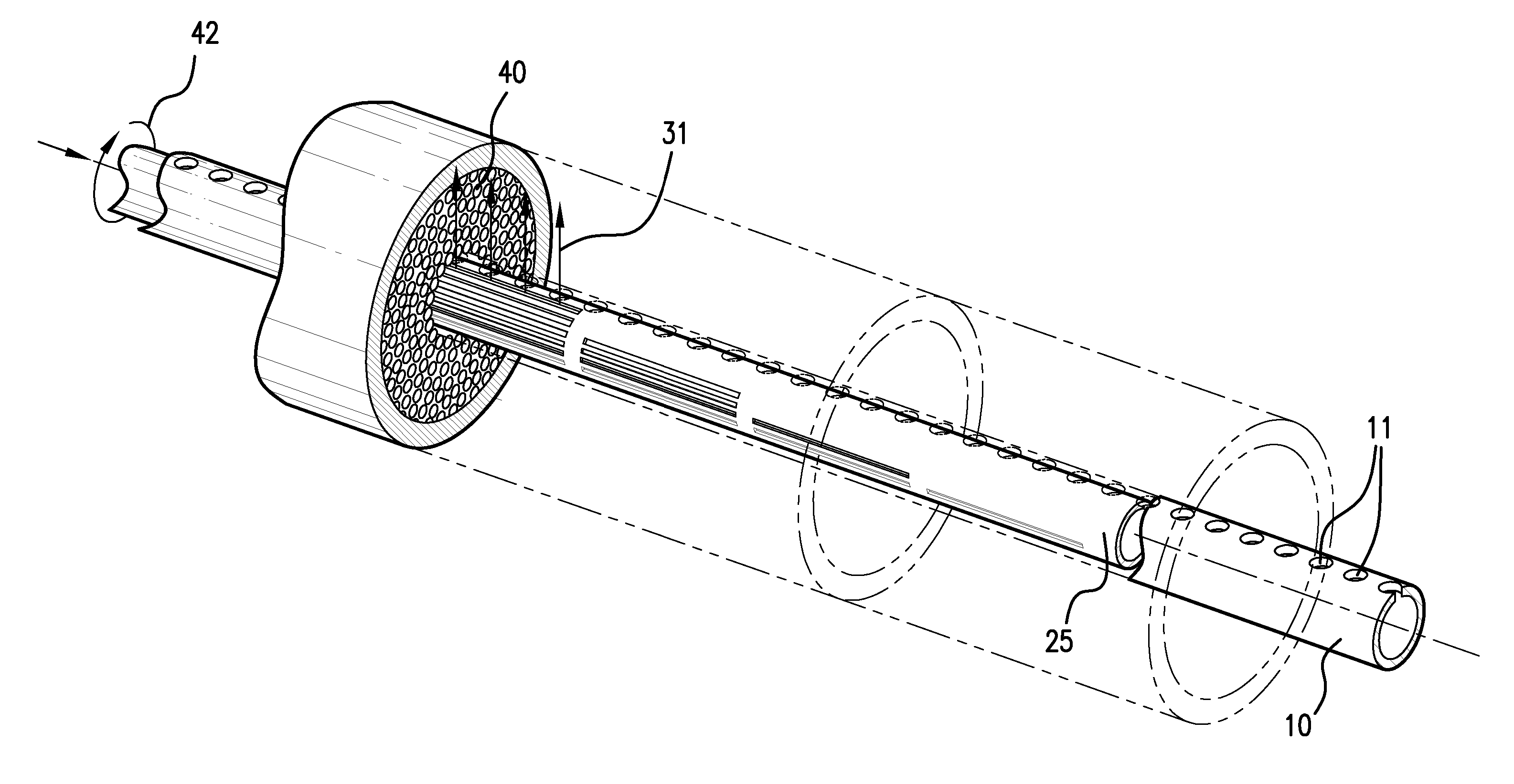
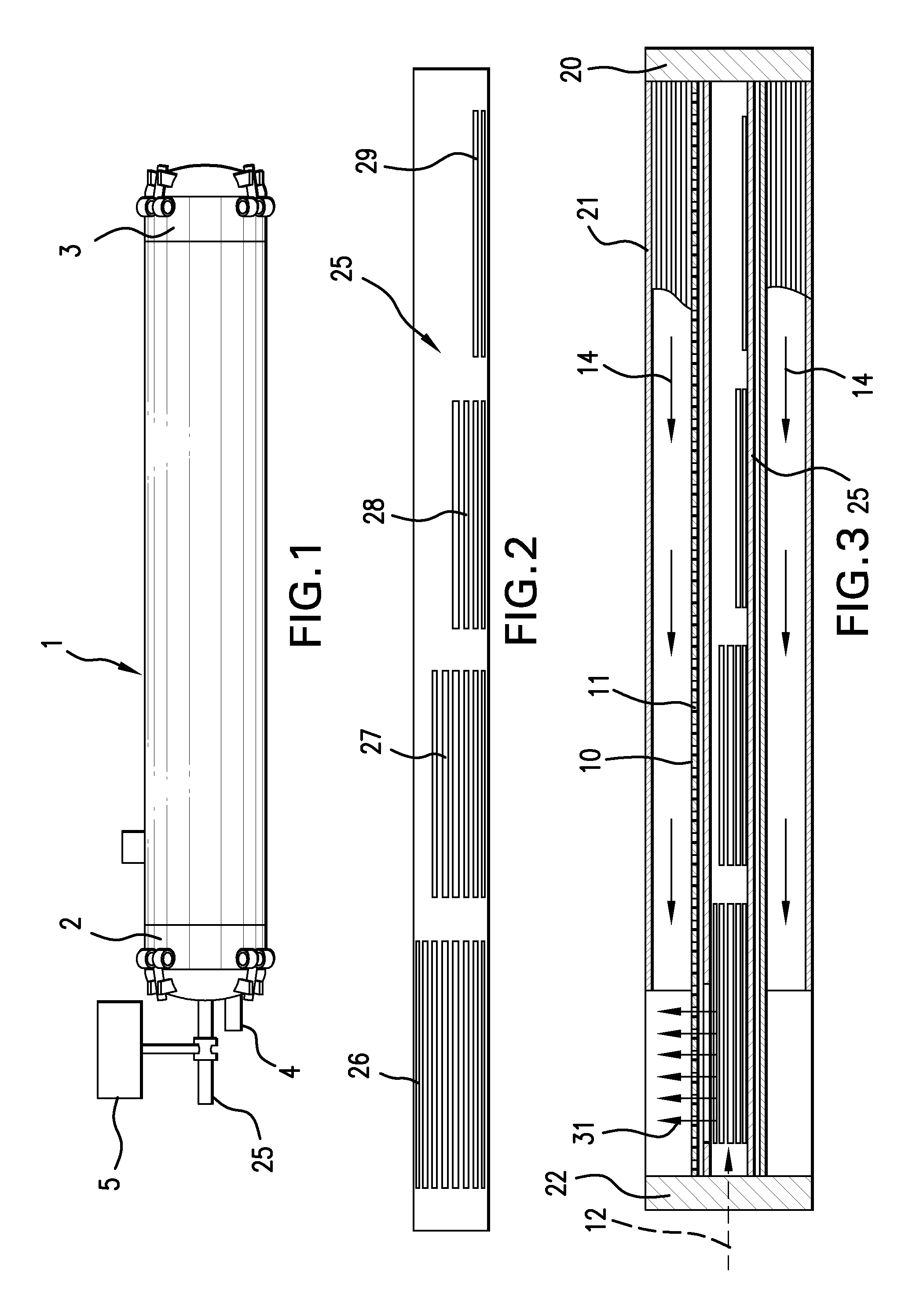
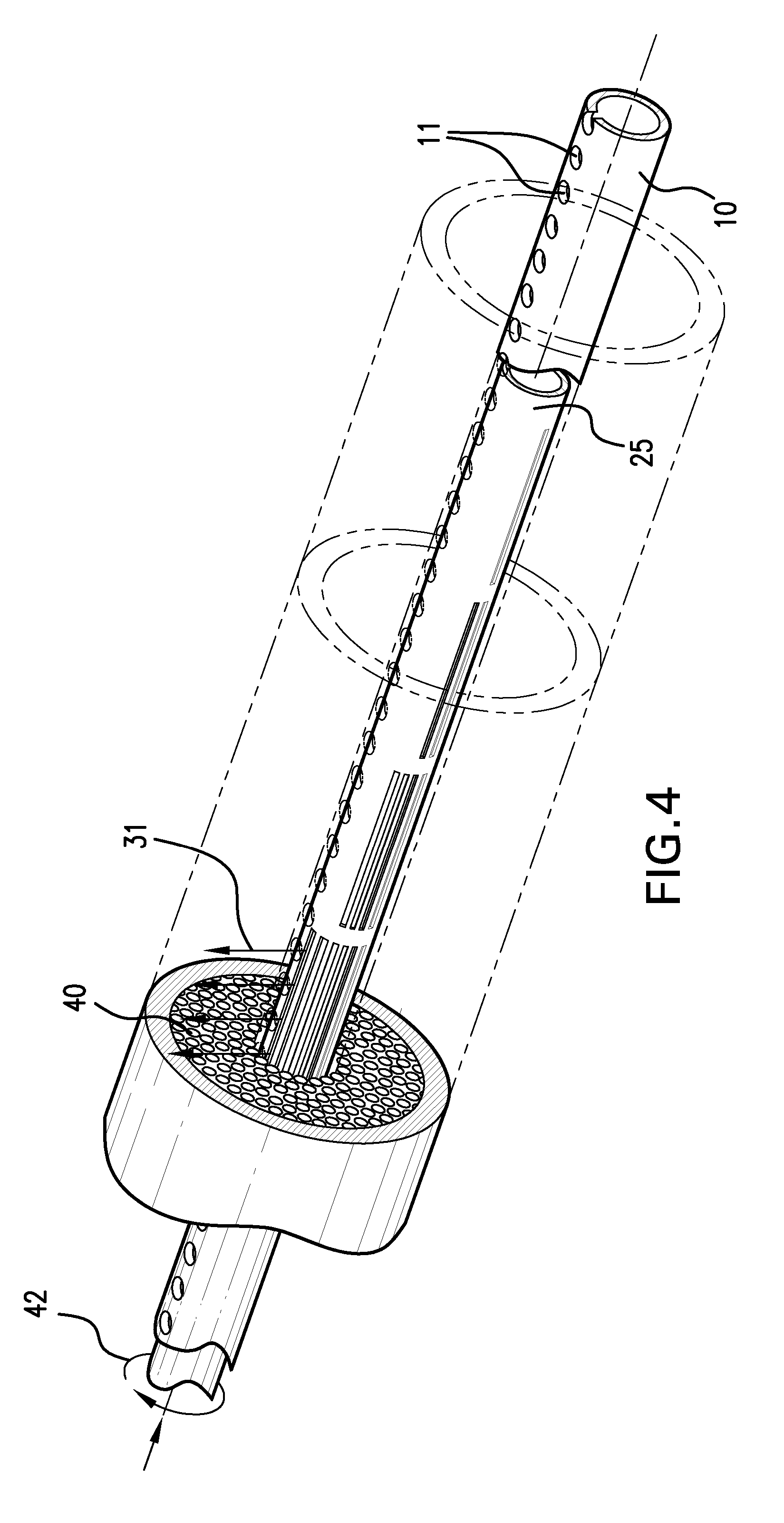
A gas-separation module allows a sweep gas to be introduced at selectively variable locations, and in selectively varying amounts, along the length of the module. The sweep gas enters the module through a perforated conduit. A slotted sleeve, disposed within the conduit, selectively blocks and unblocks perforations in the conduit. Rotation of the sleeve causes slots to come into, or out of, registration with the perforations. The sleeve permits varying amounts of sweep gas to be introduced at different locations along the length of the module. Rotation of the sleeve changes the profile of introduction of sweep gas, and can be used to optimize the performance of the module for each of a set of different pressure conditions.

Description

BACKGROUND OF THE INVENTION[0001]The present invention relates to the field of non-cryogenic separation of gases, such as air, into components.[0002]It has been known to use a polymeric membrane to separate air into components. Various polymers have the property that they allow different gases to flow through, or permeate, the membrane, at different rates. A polymer used in air separation, for example, will pass oxygen and nitrogen at different rates. The gas that preferentially flows through the membrane wall is called the “permeate” gas, and the gas that tends not to flow through the membrane is called the “non-permeate” or “retentate” gas. The selectivity of the membrane is a measure of the degree to which the membrane allows one component, but not the other, to pass through.[0003]A membrane-based gas separation system has the inherent advantage that the system does not require the transportation, storage, and handling of cryogenic liquids. Also, a membrane system requires relati...

Claims


Application Information

Patent Timeline
Patent Type & Authority Patents(United States)
IPC IPC(8): B01D53/22
CPCB01D53/22B01D63/02C01B13/0251C01B2210/0046B01D2313/26
Inventor JENSVOLD, JOHN A.
Owner GENERON IGS
Learn More