
Table edge supporting apparatus

a technology for supporting apparatus and tables, which is applied in the direction of machine supports, curtain suspension devices, other domestic objects, etc., can solve the problems of inability to reduce the overall structure in size for storage, the support hook cannot be stored within the associated housing, and the overall structure cannot be used and stored flexiblely

Inactive Publication Date: 2009-04-14
COHEN LAURIE
View PDF21 Cites 24 Cited by
  • Summary
  • Abstract
  • Description
  • Claims
  • Application Information

AI Technical Summary

Benefits of technology

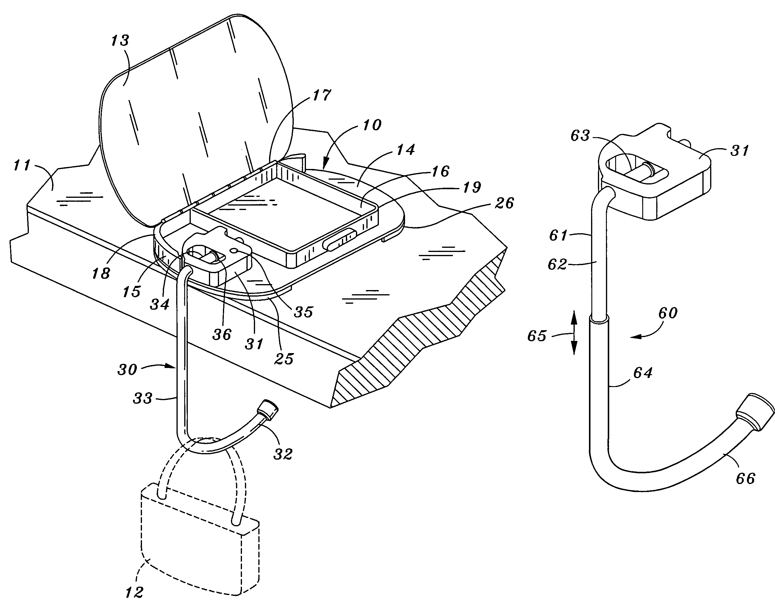
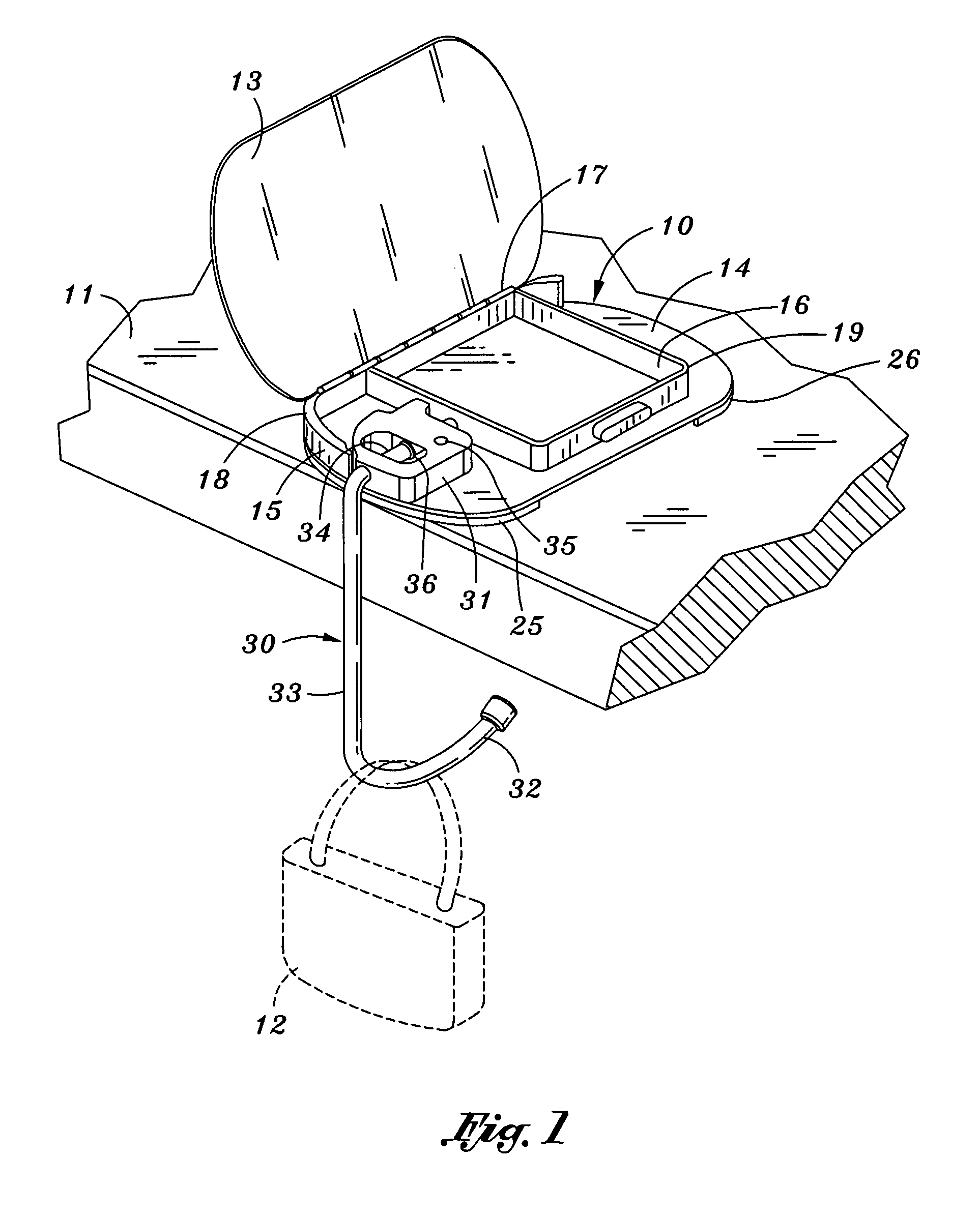
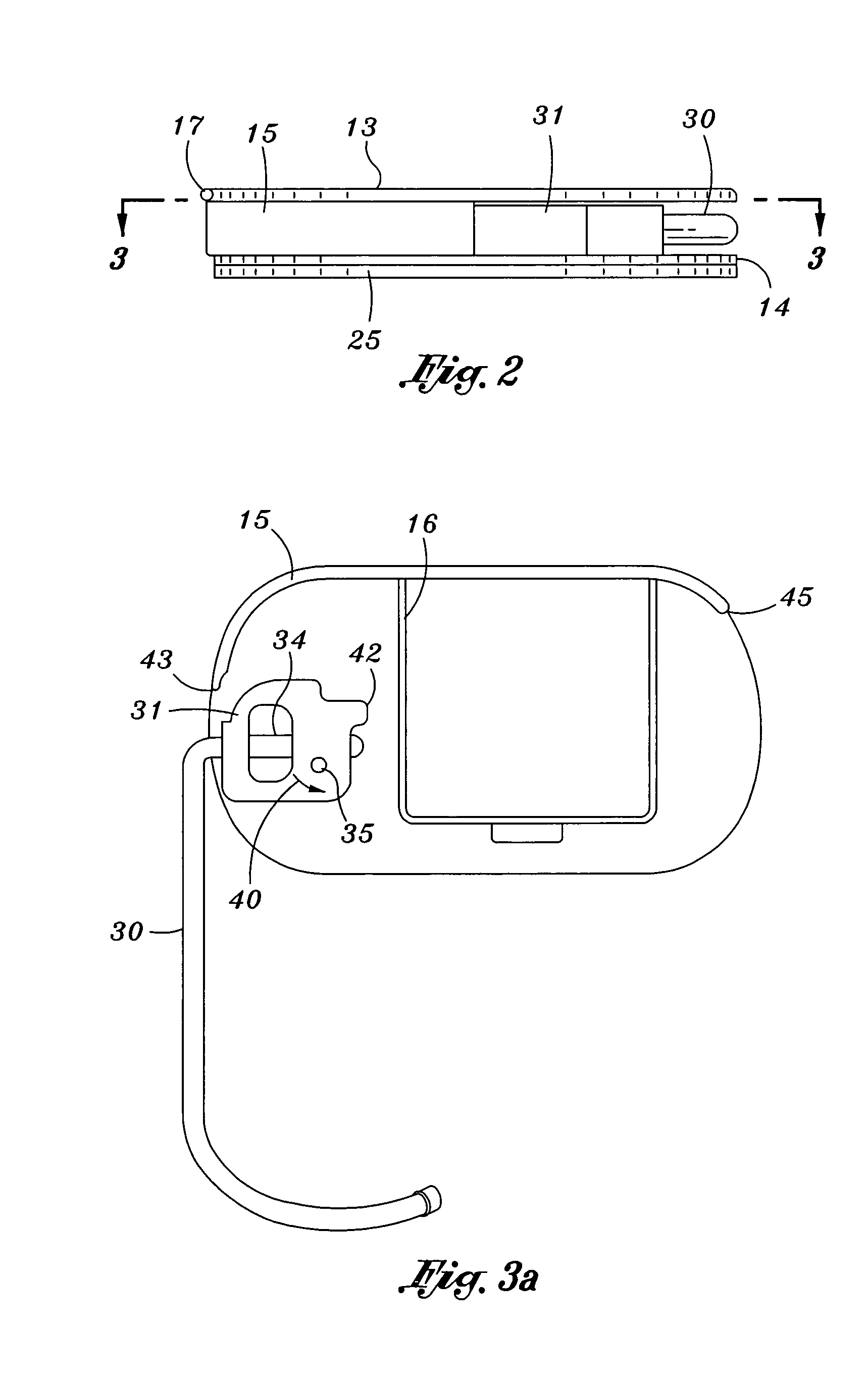
[0007]The present invention comprises a supporting apparatus to provide means for hanging or otherwise supporting purses, handbags, jackets and the like from the horizontal surface of a table or desk. A housing adapted to be disposed upon the horizontal surface of the table or desk comprises a pair of planar housing panels positioned in parallel spaced relation to one another. An interior wall having a uniform height is disposed between the housing panels and is perpendicular thereto. A pivot block is adapted to be rotatable about an axis perpendicular to the planar panels. A supporting hook is pivotally coupled to the pivot block in a manner which permits the supporting member to be rotated in two planes, one being perpendicular to that the housing panels and one plane being parallel thereto. The pivotability of the supporting member relative to the housing panels permits the supporting hook to be properly oriented relative to the desk or table when in use as well as being disposed and secured between the housing panels for storage.
[0008]It is therefore an object of the present invention to provide an improved supporting apparatus for hanging personal items from the horizontal surface of a table or desk.
[0011]It is still yet another object of the present invention to provide a supporting apparatus for purses, handbags and the like which is simple and inexpensive to fabricate.

Problems solved by technology

The problems inherent in this device primarily relate to the lack of flexibility for use and storage.
Although the C-shaped member is capable of being pivoted relative to the supporting flange, the overall structure cannot be reduced in size for storage.
However, the supporting hook cannot be stored within the associated housing.

Method used


Image

  • Table edge supporting apparatus
  • Table edge supporting apparatus
  • Table edge supporting apparatus

Examples


Embodiment Construction

[0021]An understanding of the present invention supporting apparatus can be best understood by reference to FIGS. 1-6, the present invention supporting apparatus being generally designated by the reference numeral 10. The present invention is intended to support or otherwise hang personal items such as a purse, handbag or jacket from a horizontal desk or table surface 11. In FIG. 1, the present invention supporting apparatus 10 is illustrated supporting a handbag 12.

[0022]The present invention 10 embodies a housing consisting of a top panel 13 and a bottom panel 14 in parallel spaced relation to each other. The relative position of panels 13 and 14 are maintained by an interior wall comprised of elements 15 and 16 are perpendicular to top and bottom panels 13 and 14. The interior walls 15 and 16 are uniform in height. Although FIG. 1 illustrates an interior wall comprised of a pair of interior wall elements 15 and 16, it is understood interior walls 15 and 16 may be constructed in a...


PUM


Abstract

A handbag 12 is supported from a table surface 11. A hook 30 extends from the space between parallel panels 13 and 14 and includes a segment 34 rotatable with pivot block 31 between the panels. In one position (FIG. 1), hook 30 is perpendicular to panels 13 and 14 to support the handbag 12. Hook 30 is rotatable in directions 41 (FIG. 5) to a position between, and parallel to, the panels. Hook 30 is coupled to a pivot 35 to rotate with pivot block 31 in a horizontal plane to a storage position. In this position, hook 43 is fixedly positioned relative to magnet 35. To prevent the hook 30 from being dislodged from surface 11, non-skid members are secured to the bottom surface of panel 14.

Description

BACKGROUND OF THE INVENTION[0001]1. Field of the Invention[0002]The present invention generally relates to apparatus used to hang or support personal items such as purses or jackets and, more particular, to supporting apparatus employed to support items from the horizontal surface of a table, desk or the like.[0003]2. Prior Art[0004]The prior art discloses numerous devices which are used to hold handbags, purses and the like from the edge of an elevated, horizontal platform such as a table. As a general rule, the devices disclosed by the prior art are intended to be small in size and sufficiently small to be maintained by the user in his or her jacket or handbag.[0005]One of the devices disclosed by the prior art for hanging or otherwise supporting handbags at the edge or periphery of a table, desk or other horizontal support employs an upper member having a first flange adapted to be placed adjacent the support surface and a second flange secured to the first flange extending downw...

Claims


Application Information

Patent Timeline
Patent Type & Authority Patents(United States)
IPC IPC(8): F16B45/00
CPCA47G29/083Y10S248/914Y10S248/917
Inventor BRUSTEIN, ALISONCOHEN, LAURIE
Owner COHEN LAURIE
Learn More