Controlled odor generator
- Summary
- Abstract
- Description
- Claims
- Application Information
AI Technical Summary
Benefits of technology
Problems solved by technology
Method used
Image
Examples
Embodiment Construction
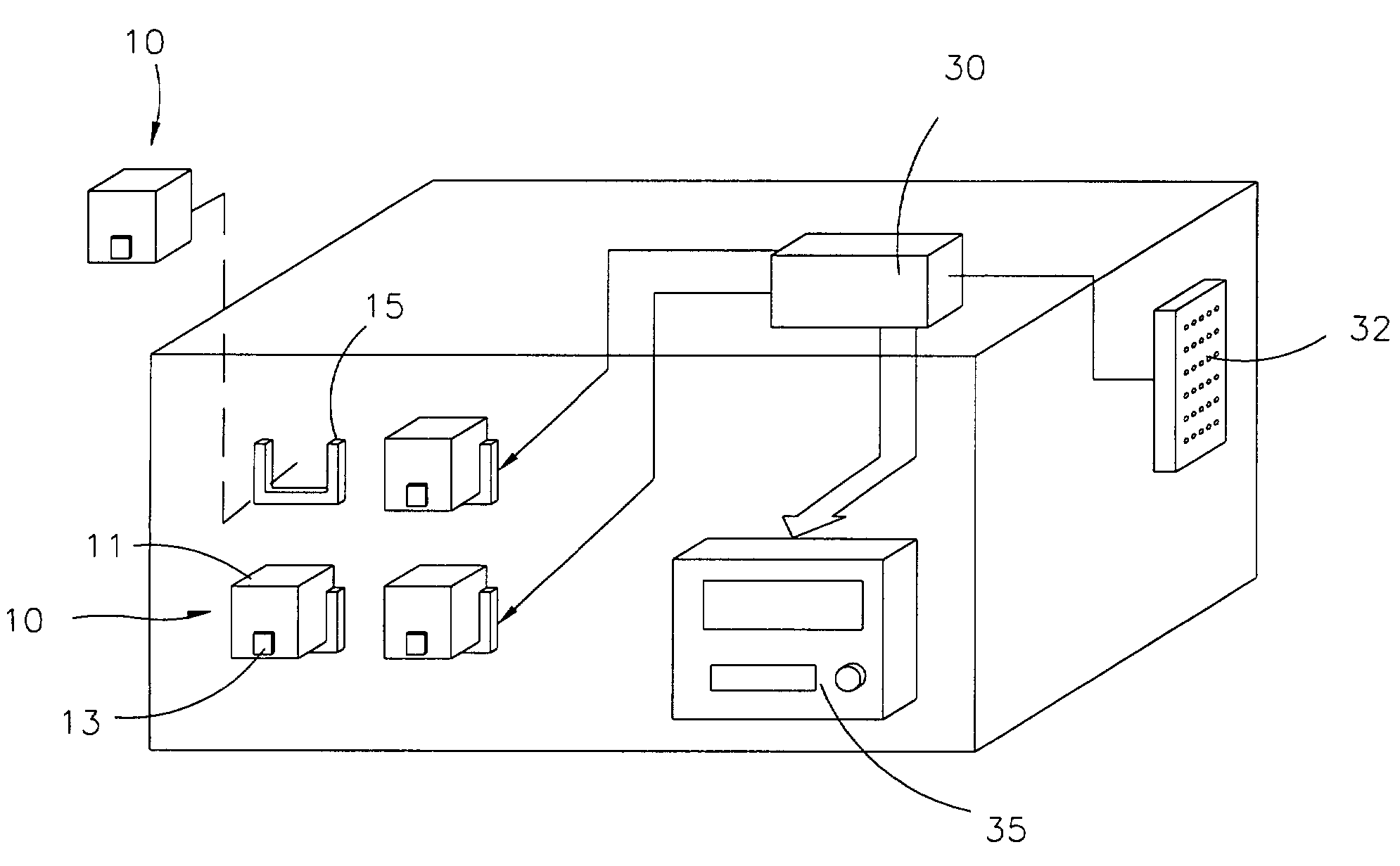
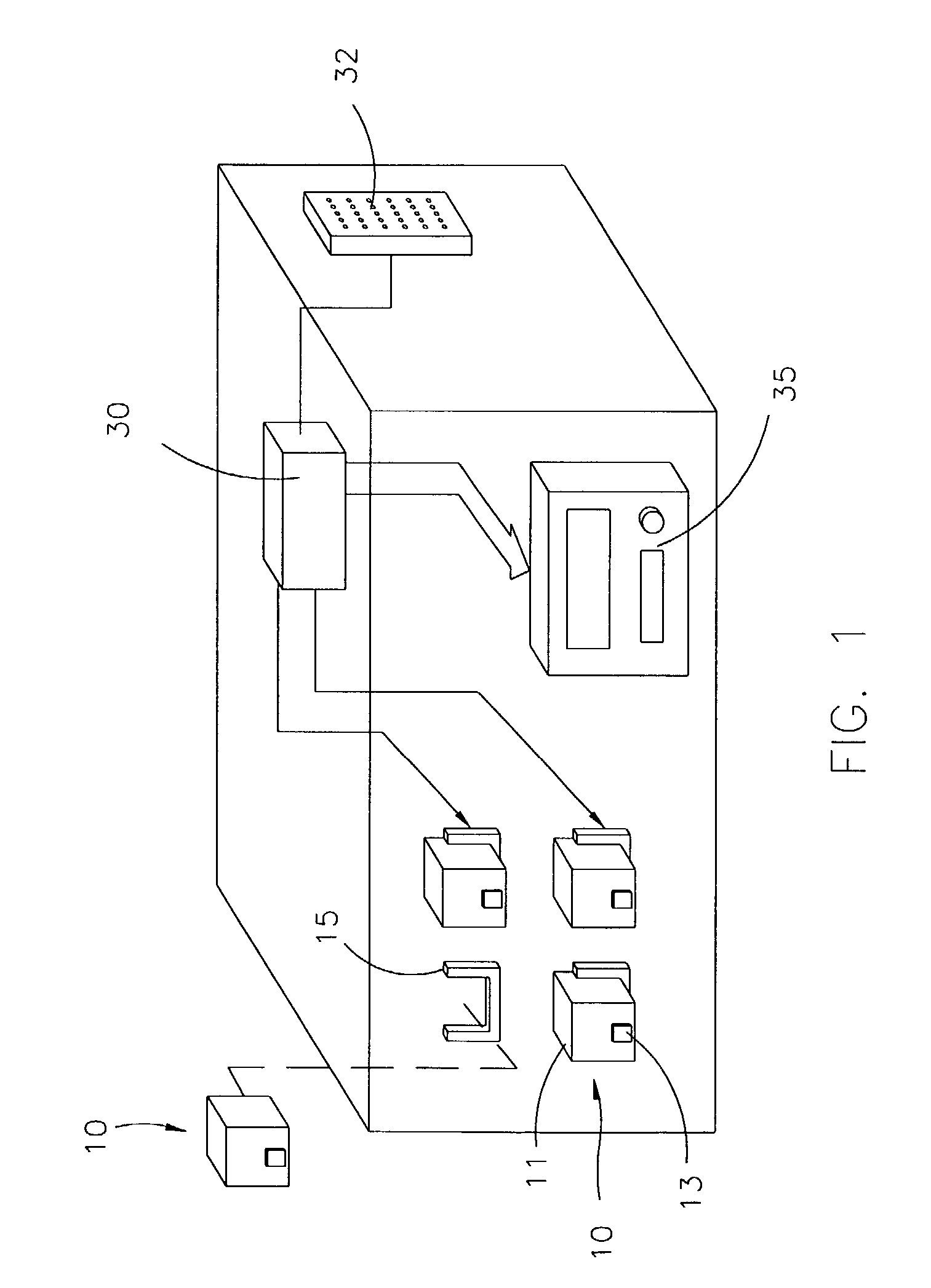
[0021]As shown in FIG. 1, the controlled odor generator of the present invention mainly comprises: at least one micropump unit 10; a central processing unit 30 for controlling the micropump units 10, having a connector 32 for receiving signals; and a control panel 35, allowing manual setting of signals.
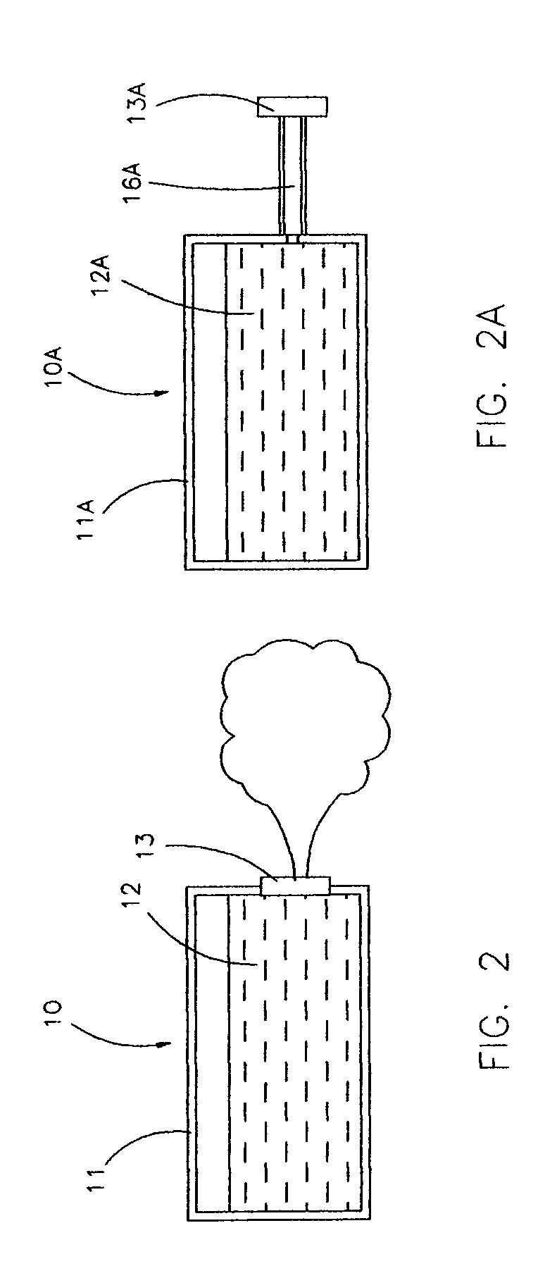
[0022]As shown in FIG. 2, each of the micropump units 10 comprises: a casing 11, filled with odorous fluid 12; a base 15, on which the casing 11 is set, so that the casing 11 is replaceable; and a micropump array 13, vaporizing and ejecting the odorous fluid 12 by micropulsation, thus generating odor in the environment.
[0023]In the embodiment of the present invention shown in FIG. 2, the micropump array element 13 is integral with the casing 11 and is thus replaced along with the casing 11. Another embodiment of the present invention, shown in FIG. 2A, has a micropump unit 10A with a casing 11A and a micropump array element 13A which are separated, being connected by a tube 16A.
[0024]...
PUM
| Property | Measurement | Unit |
|---|---|---|
| Temperature | aaaaa | aaaaa |
| Density | aaaaa | aaaaa |
| Humidity | aaaaa | aaaaa |
Abstract
Description
Claims
Application Information
 - R&D
- Intellectual Property
- Life Sciences
- Materials
- Tech Scout
- Unparalleled Data Quality
- Higher Quality Content
- 60% Fewer Hallucinations
Browse by: Latest US Patents, China's latest patents, Technical Efficacy Thesaurus, Application Domain, Technology Topic, Popular Technical Reports.
© 2025 PatSnap. All rights reserved.Legal|Privacy policy|Modern Slavery Act Transparency Statement|Sitemap|About US| Contact US: help@patsnap.com


