
Spike mold structure

a mold and mold technology, applied in the field of mold structure, can solve problems such as user injuries, and achieve the effects of reducing manpower costs, improving strength, and increasing manufacturing efficiency

Inactive Publication Date: 2009-04-07
LIAO I CHUNG
View PDF10 Cites 37 Cited by
  • Summary
  • Abstract
  • Description
  • Claims
  • Application Information

AI Technical Summary

Benefits of technology

"The present invention provides a spike mold structure that improves strength and efficiency in molding spikes with two colors. The mold structure includes a male mold base and a female mold base with a plurality of molds and sliding rods that can be moved within a limited distance. The molds are designed to have concave slots and convex blocks that make the two molds insert into each other and push and contact each other. The mold structure also includes thimbles that are plugged into the molds and a thimble base that can be rotated to fit in with the molds. The spike mold structure molds the spike by two continuous injection molding processes to increase strength."

Problems solved by technology

There further exists a problem of the spike dropping from the shoe that causes users to be hurt when they are exercising.

Method used


Image

  • Spike mold structure
  • Spike mold structure
  • Spike mold structure

Examples


first embodiment

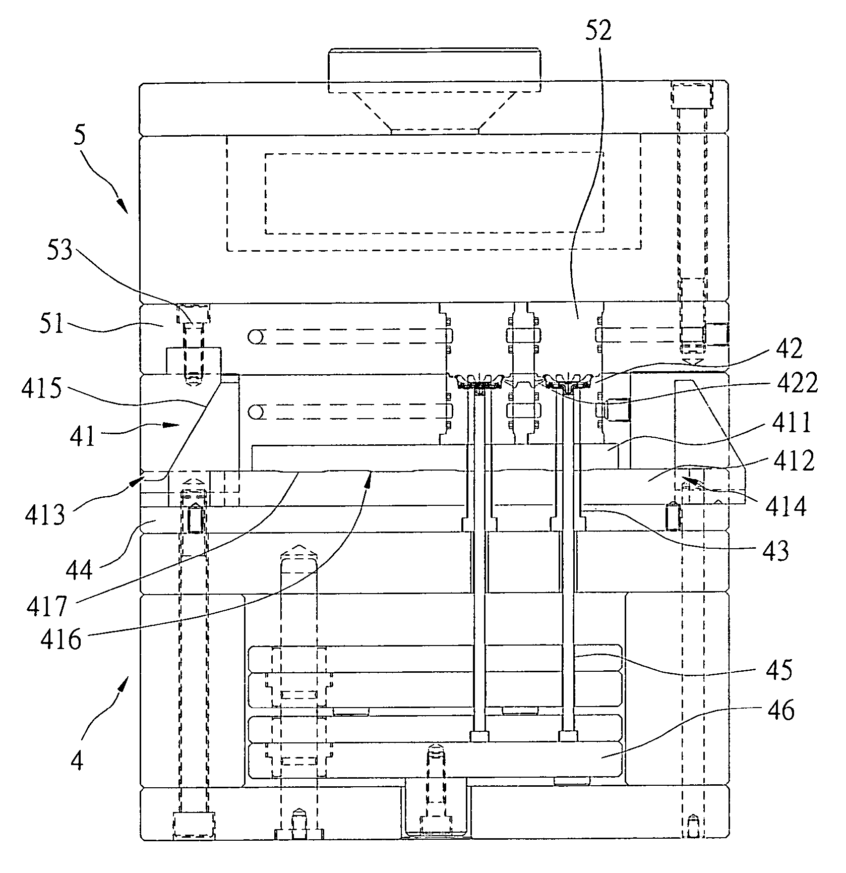
[0041]Reference is made to FIGS. 3 and 10, which shows the present invention. The spike mold structure includes a first male mold base 3, a second male mold base 5, and at least one female mold base 4. The first male mold base 3 and the second male mold base 5 individually correspond to the female mold base 4.

[0042]The first male mold base 3 includes a first male mold fixing base 31, a plurality of first male molds 32, and at least one firing pin 33. The first male molds 32 are located at the first male mold fixing base 31. The firing pin 33 is located at one side of the first male mold fixing base 31. At an inner part of each of the first male molds 32, a runner 321 is formed (as shown in FIGS. 5A and 5B). The plastic material is injected from the runners 321.

[0043]The second male mold base 5 includes a second male mold fixing base 51, a plurality of second male molds 52, and at least one firing pin 53. The second male molds 52 (FIG. 6) are located at the second male mold fixing ba...

second embodiment

[0053]Reference is made to FIG. 13, which shows the present invention. The spike mold structure includes a male mold base 6, and a female mold base 4 that correspond to each other.

[0054]The male mold base 6 includes a male mold fixing base 61, a plurality of first male molds 62, a plurality of second male molds 63, and at least two firing pins 64. The first male molds 62 and the second male molds 63 are symmetrically located at two sides of the male mold fixing base 61. The firing pins 64 are also located at the male mold fixing base 61, and are located at the same side that corresponds to the first male mold 62 and the second male mold 63.

[0055]The female mold base 4 includes two first female mold fixing bases 41, a second female mold fixing base 44, a plurality of thimbles 45, and two thimble bases 46, a plurality of first female molds 47, a plurality of second female molds 48, and a plurality of third female molds 49. The two first female mold fixing bases 41 correspond to the fi...


PUM

PropertyMeasurementUnit
structureaaaaaaaaaa
colorsaaaaaaaaaa
coloraaaaaaaaaa

Abstract

A spike mold structure includes a first male mold base having a plurality of male molds and at least one firing pin, and a female mold base having a first fixing board, a second fixing board, a plurality of outer female molds and inner female mold. The second fixing board has at least one sliding rod, and the sliding rod has an actuating block. One surface of the first fixing board has a plurality of convex blocks. A plurality of concave slots are located at the surface of the sliding rod. The thimbles push the actuating block to make the sliding rod slidingly move so that the first fixing board and second fixing board are closely embedded or have a gap. Therefore, there is a displacement between the outer and the inner female mold. The spike mold structure is used to mold a bi-colored spike having increased strength.

Description

BACKGROUND OF THE INVENTION[0001]1. Field of the Invention[0002]The present invention relates to a spike mold structure. In particular, this invention relates to a spike mold structure that can be formed via two continuous processes.[0003]2. Description of the Related Art[0004]The golf spike (sometimes also known as a cleat), such as the spike published in Taiwan patent T.W. 588980, and the spike set published in Taiwan patent T.W. 266736, includes a connection part and a spike part. The connection part is usually made of metal or macromolecule material and is formed by an injection molding process. The spike part is made of macromolecule material and is formed on the connection part by an injection molding process.[0005]Generally, when a spike is manufactured, two steps are needed. Firstly, the connection part is manufactured. Then, the spike part is molded on the connection part. When the connection part is made of metal, the spike is molded on the connection via an injection mold...

Claims


Application Information

Patent Timeline
Patent Type & Authority Patents(United States)
IPC IPC(8): B29C45/14
CPCB29C45/062B29C45/162B29C45/1671B29C45/2673
Inventor LIAO, I-CHUNG
Owner LIAO I CHUNG
Learn More