Piston head for hydraulic injection molding machine
a hydraulic injection molding machine and piston head technology, applied in mechanical equipment, water mains, service pipe systems, etc., can solve the problems that the effect of maximum stress reduction or stress regularization cannot be expected, and achieve the effect of reducing the maximum stress
- Summary
- Abstract
- Description
- Claims
- Application Information
AI Technical Summary
Benefits of technology
Problems solved by technology
Method used
Image
Examples
first embodiment
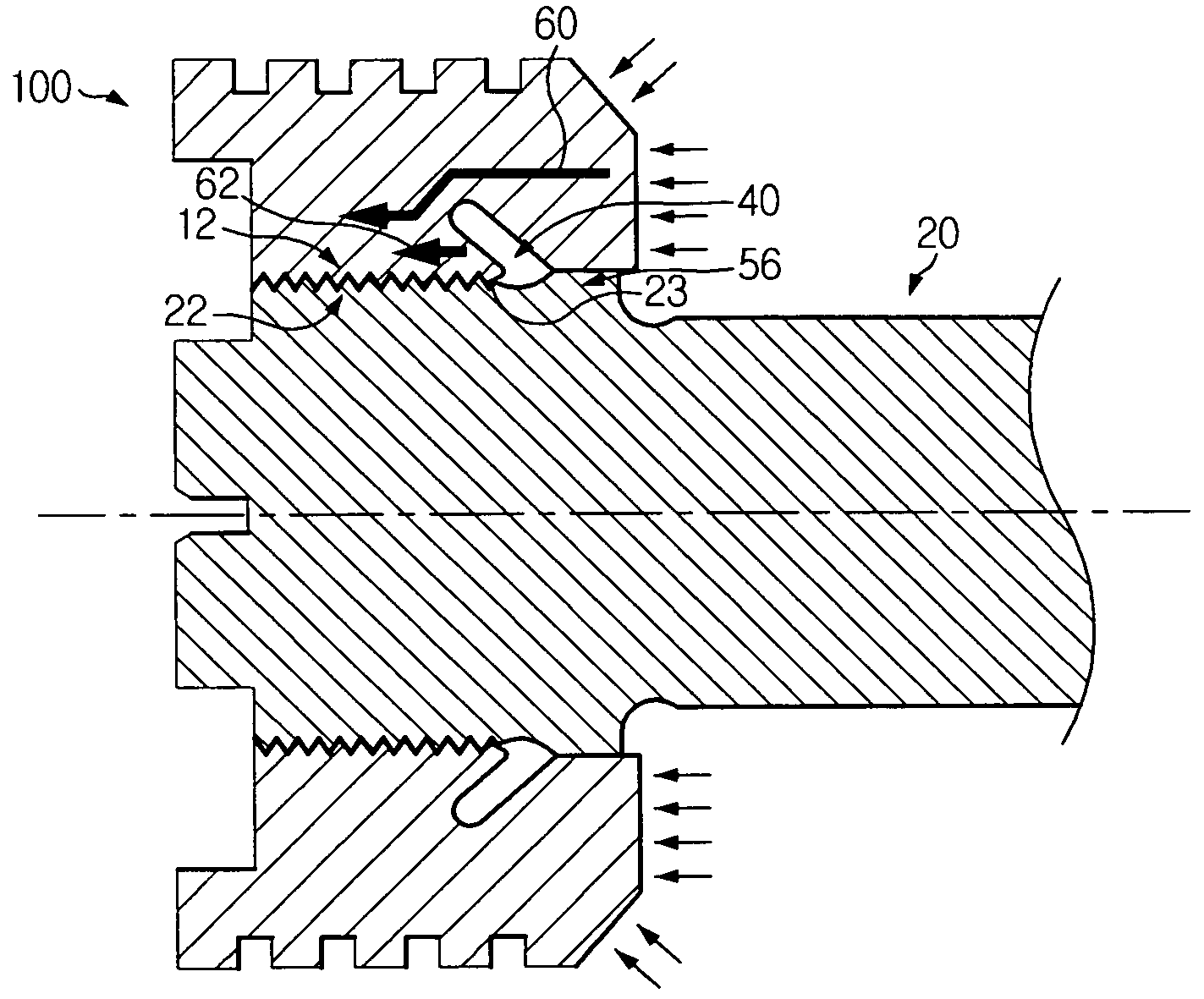
[0027]FIG. 3 is a sectional view showing a piston head coupled with a tie rod according to the present invention.
[0028]Referring to FIG. 3, the piston head 100 has an insert groove 40 formed with a slope. The piston head 100 is screwed with a tie rod 20. A first screw 22 is formed on an outer circumference of the tie rod 20, and a second screw 12 engaged with the first screw 22 is formed in an inner circumference of a hollow of the piston head 100. The tie rod 20 is screwed into the hollow of the piston head 100.
[0029]The insert groove 40 is formed to be inclined toward the rear of the piston head 20. The insert groove 40 is formed in front of the second screw 12, and preferably formed between the second screw 12 and an oil sealing unit 56 for preventing inflow of oil. It allows to effectively reduce a maximum stress generated at a first root 23 of the first screw 22.
[0030]In addition, the insert groove 40 is preferably formed in a circumferential direction of the inner circumferenc...
second embodiment
[0032]FIG. 4 is a sectional view showing a piston head screwed with a tie rod according to the present invention. The piston head 100a has an insert groove 40a formed to a predetermined depth perpendicularly to an inner circumference of a hollow of the piston head 100a and then bent backward. Preferably, the insert groove 40a has a section in a ‘L’ shape.
third embodiment
[0033]FIG. 5 is a sectional view showing a piston head screwed with a tie rod according to the present invention. This piston head 100b has an insert groove 40b formed to be perpendicular to an inner circumference of a hollow of the piston head. Meanwhile, in FIGS. 4 and 5, the same reference numeral as in FIG. 3 designates the same component having the same function.
[0034]The insert groove 40a, 40b is formed in front of the second screw 12, and preferably formed between the second screw 12 and the oil sealing unit 56 that prevents inflow of oil. In addition, the insert groove 40a, 40b is preferably formed in a circumference direction of the inner circumference. A stress distribution on the first screw 22 is shown in FIG. 6.
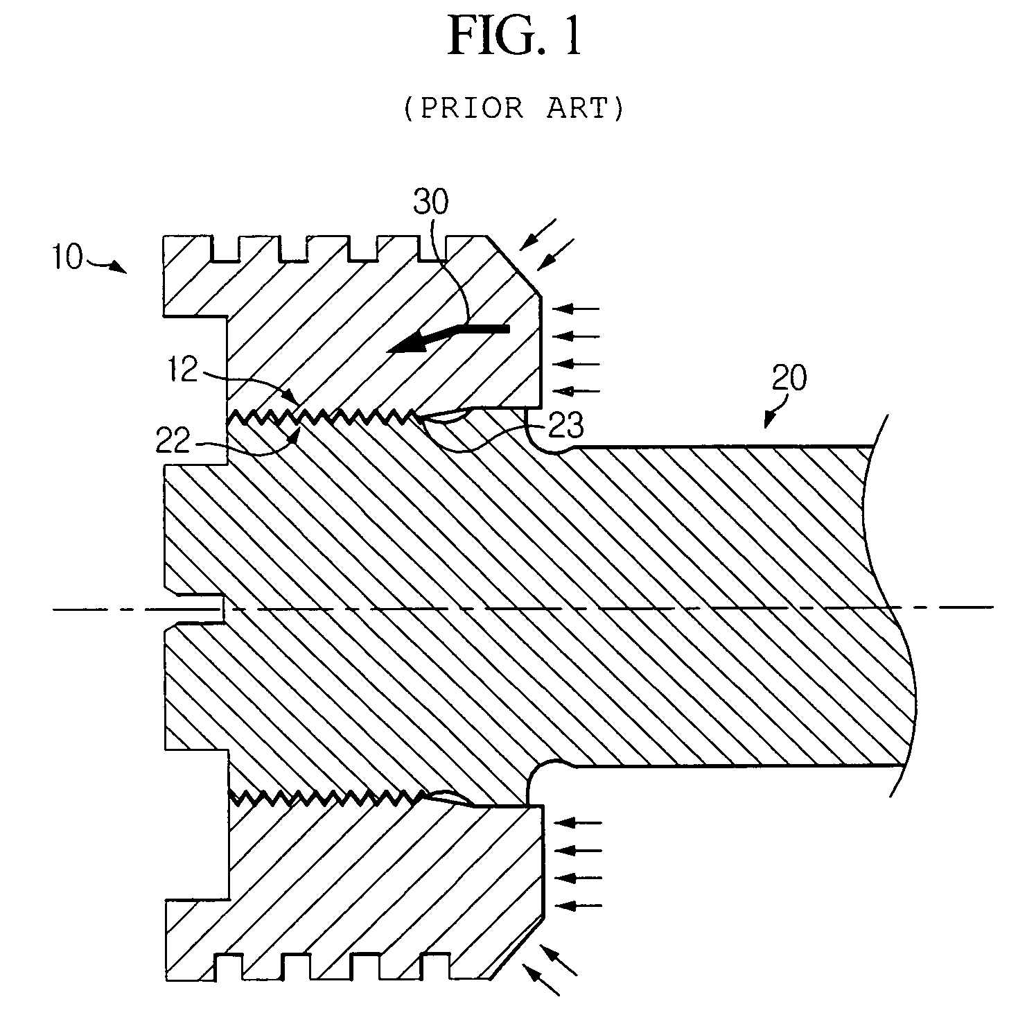
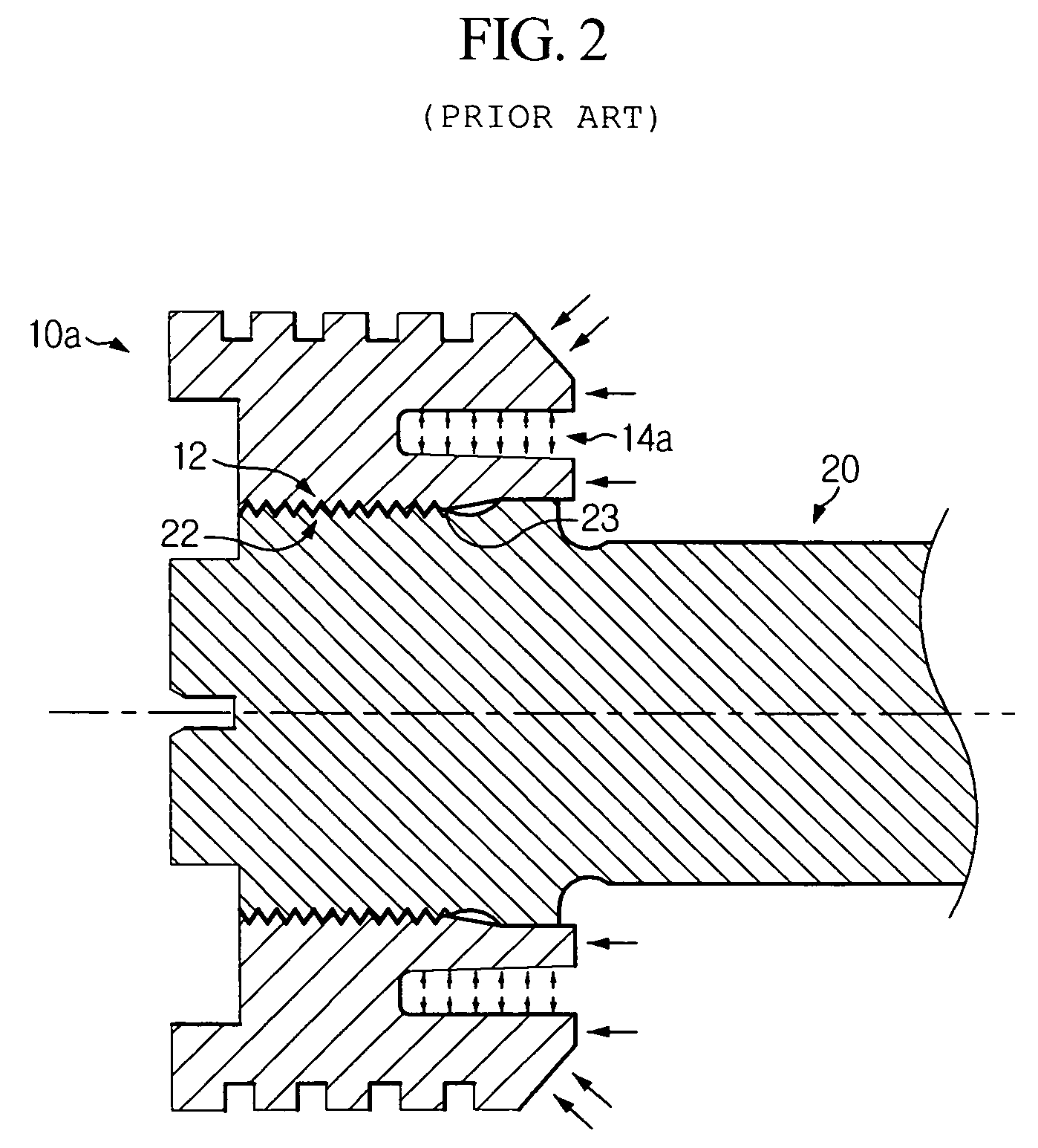
[0035]As mentioned above, the insert groove 40, 40a, 40b formed in the piston head 100, 100a, 100b decreases a maximum stress applied to the first screw 22. As shown in FIG. 6, a maximum stress occurs at the first root 23 in case of a general piston head 10 (see ...
PUM
| Property | Measurement | Unit |
|---|---|---|
| circumference | aaaaa | aaaaa |
| depth | aaaaa | aaaaa |
| stress | aaaaa | aaaaa |
Abstract
Description
Claims
Application Information
 - R&D
- Intellectual Property
- Life Sciences
- Materials
- Tech Scout
- Unparalleled Data Quality
- Higher Quality Content
- 60% Fewer Hallucinations
Browse by: Latest US Patents, China's latest patents, Technical Efficacy Thesaurus, Application Domain, Technology Topic, Popular Technical Reports.
© 2025 PatSnap. All rights reserved.Legal|Privacy policy|Modern Slavery Act Transparency Statement|Sitemap|About US| Contact US: help@patsnap.com


