
Backplane interface adapter

a backplane interface and adapter technology, applied in the field of network switches, can solve the problems of limiting the bit carrying capacity of many switches to the switch fabric, and the switch fabric would be unable to handle the increased traffi

Inactive Publication Date: 2009-03-31
AVAGO TECH INT SALES PTE LTD
View PDF209 Cites 59 Cited by
  • Summary
  • Abstract
  • Description
  • Claims
  • Application Information

AI Technical Summary

Benefits of technology

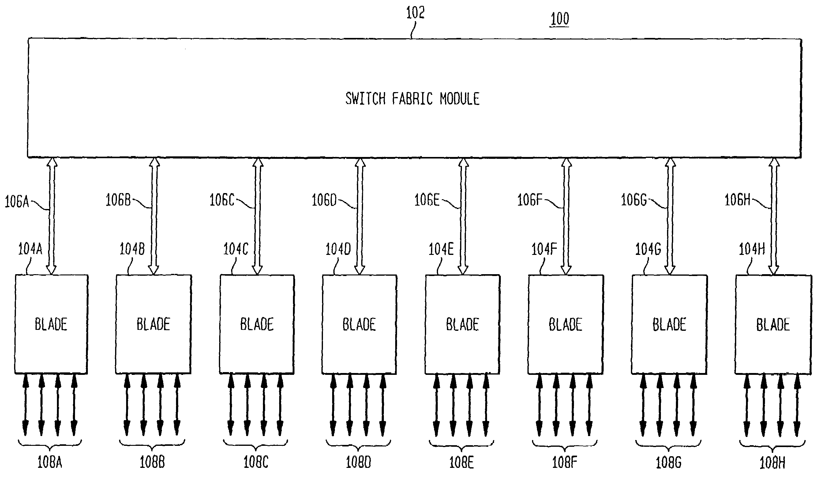
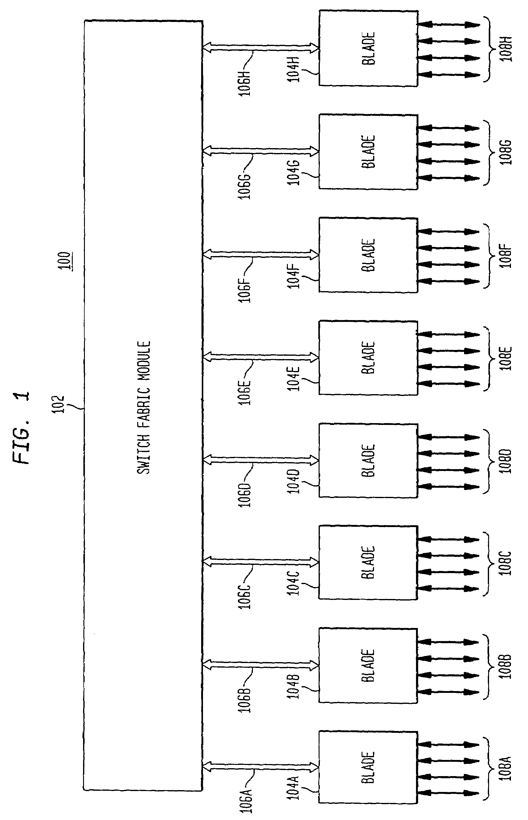
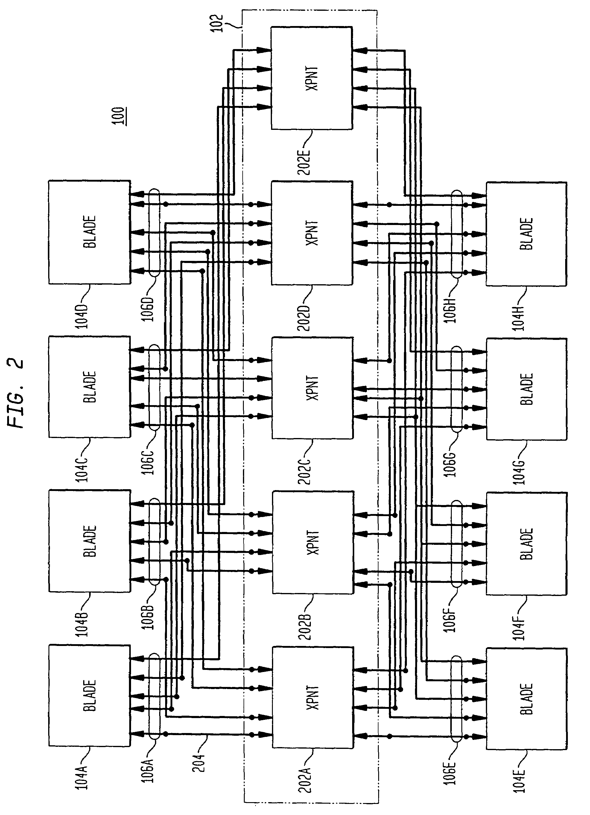
[0016]In one embodiment of the present invention, each blade has a backplane interface adapter (BIA). The BIA has three traffic processing flow paths. The first traffic processing flow path extends in traffic flow direction from local packet processors toward a switching fabric. The second traffic processing flow path extends in traffic flow direction from the switching fabric toward local packet processors. A third traffic processing flow path carried local traffic from the first traffic processing flow path. This local traffic is sorted and routed locally at the BIA without having to go through the switching fabric.

Problems solved by technology

A limiting factor in the bit carrying capacity of many switches is the switch fabric.
However, the switch fabric would be unable to handle the increased traffic.

Method used


Image

  • Backplane interface adapter
  • Backplane interface adapter
  • Backplane interface adapter

Examples


Embodiment Construction

Table of ContentsI.Overview and DiscussionII.TerminologyIII.Digital Switch ArchitectureA.Cross Point ArchitectureB.Port Slice Operation with Wide Cell Encoding and Flow ControlC.Backplane Interface AdapterD.Overall Operation of Backplane Interface AdapterE.First Traffic Processing PathF.Narrow Cell FormatG.Traffic SortingH.Wide Striped Cell GenerationI.Encoding Wide Striped CellsJ.Initial Block EncodingK.End of Packet EncodingL.Switching Fabric Transmit ArbitrationM.Cross Point Processing of StripesN.Second Traffic Processing PathO.Cell Boundary AlignmentP.Packet AlignmentQ.Wide Striped Cell Size at Line RateR.IBT and Packet ProcessingS.Narrow Cell and Packet Encoding ProcessesT.Administrative Process and Error ControlU.Reset and Recovery ProceduresIV.Control LogicV.Conclusion

I. OVERVIEW AND DISCUSSION

[0071]The present invention is a high-performance digital switch. Blades are coupled through serial pipes to a switching fabric. Serial link technology is used in the switching fabric....


PUM


Abstract

A backplane interface adapter for a network switch. The backplane interface adapter includes at least one receiver that receives input cells carrying packets of data; at least one cell generator that generates encoded cells which include the packets of data from the input cells; and at least one transmitter that transmits the generated cells to a switching fabric. The cell includes a destination slot identifier that identifies a slot of the switching fabric towards which the respective input cell is being sent. The generated cells include in-band control information.

Description

CROSS-REFERENCE TO RELATED APPLICATIONS[0001]This application is a continuation of application Ser. No. 09 / 855,038, filed May 15, 2001 now U.S. Pat. No. 7,236490, which claimed the benefit of Provisional. App. 60 / 249,871, filed Nov. 17, 2000, both of which are incorporated herein by reference in their respective entireties. Other related applications include U.S. patent applications 09 / 988,066, 09 / 855,015, 10 / 810,301, and 11 / 724,965. Related patents include U.S. Pat. Nos. 6,697,368, 6,735,218, 6,901,072, 7,203,194, and 7,206,238.BACKGROUND OF THE INVENTION[0002]1. Field of the Invention[0003]The invention relates generally to network switches.[0004]2. Background Art[0005]A network switch is a device that provides a switching function (i.e., determines a physical path) in a data communications network. Switching involves transferring information, such as digital data packets or frames, among entities of the network. Typically, a switch is a computer having a plurality of circuit card...

Claims


Application Information

Patent Timeline
Patent Type & Authority Patents(United States)
IPC IPC(8): H04L12/28H04L1/00H04L12/54H04L12/56
CPCH04L12/5693H04L47/6225H04L49/153H04L49/1538H04L49/25H04L49/30H04L49/3063H04L49/90H04L49/901H04L49/352Y10S370/907H04L47/50
Inventor CHANG, ANDREWPATELWONG, MING G.
Owner AVAGO TECH INT SALES PTE LTD
Learn More