
Discharge lamp and illumination apparatus with gas fill

a technology of discharge lamp and illumination apparatus, which is applied in the direction of discharge tube luminescnet screen, gas-filled discharge tube, low-pressure discharge lamp, etc., can solve the problems of unavoidable lowering of luminous efficiency and unsuitable applications, and achieve the effect of improving luminous efficiency of discharge lamp, reducing power consumption and increasing brightness

Inactive Publication Date: 2009-03-24
SONY CORP
View PDF9 Cites 3 Cited by
  • Summary
  • Abstract
  • Description
  • Claims
  • Application Information

AI Technical Summary

Benefits of technology

The solution results in increased luminous efficiency, reduced power consumption, and smaller lamp size, suitable for compact applications like small device backlights, while prolonging the lamp's life and maintaining high brightness.

Problems solved by technology

However, since the related-art hot cathode type discharge lamp is as large as about 20 mm in diameter, it is not suitable for the application as a backlight of a liquid-crystal display of a small device.
On the other hand, since the cold cathode type discharge lamp is large in voltage drop in the cathode, its luminous efficiency is lowered unavoidably.

Method used


Image

  • Discharge lamp and illumination apparatus with gas fill
  • Discharge lamp and illumination apparatus with gas fill
  • Discharge lamp and illumination apparatus with gas fill

Examples


Embodiment Construction

[0027]The present invention will now be described in detail with reference to the drawings.

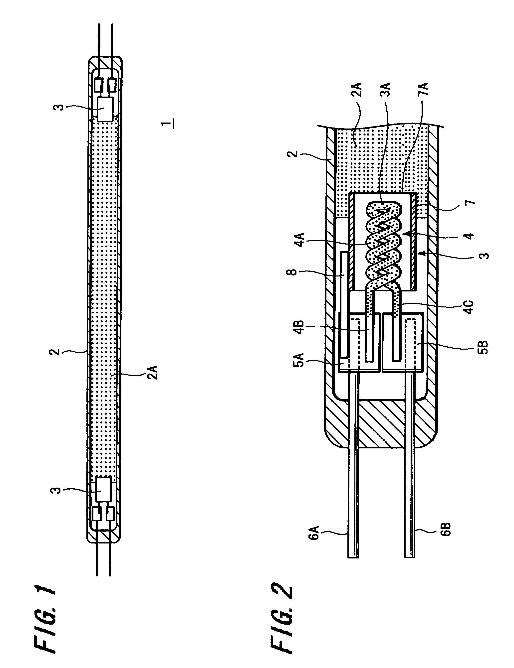
[0028]FIG. 1 of the accompanying drawings is a schematic diagram showing an arrangement of a discharge lamp according to an embodiment of the present invention.

[0029]A discharge lamp, generally depicted by reference numeral 1 in FIG. 1, includes a long and narrow glass tube 2 with electrodes 3 attached to its respective end portions, and two lead wires (lead-in wires) are connected to the two electrodes 3.

[0030]As shown in FIG. 1, a fluorescent substance layer 2A (also see FIG. 2) is formed on the inner surface of the glass tube 2.

[0031]Also, the glass tube 2 has a rare gas such as argon (Ar) gas and mercury (Hg) serving as a luminescent material sealed into the inside thereof.

[0032]FIG. 2 is a diagram showing components provided near the electrode 3 at the left end portion of the discharge lamp 1 shown in FIG. 1 in an enlarged-scale;

[0033]As shown in FIG. 2, the electrode 3 includes a heater ...


PUM

PropertyMeasurementUnit
total pressureaaaaaaaaaa
diameteraaaaaaaaaa
power consumptionaaaaaaaaaa

Abstract

A discharge lamp includes a glass tube having electrodes with an electron emissive material coated thereon, the electrodes being provided on respective ends of the glass tube, wherein the glass tube has a gas containing a luminescent material sealed therein and has a fluorescent material coated on its inner surface, the glass tube has a diameter less than 6.5 mm and the gas sealed into the glass tube is gases of more than one kind selected from an Ar (argon) gas , a Kr (krypton) gas and a Xe (xenon) gas or a mixed gas mainly made of gases of more than one kind selected from the Ar gas, the Kr gas and the Xe gas. Thus, the discharge lamp can reduce a diameter of its tube and it is able to provide high luminous efficiency.

Description

CROSS REFERENCES TO RELATED APPLICATIONS[0001]The present invention contains subject matter related to Japanese Patent Application JP 2005-087101 filed in the Japanese Patent Office on Mar. 24, 2005, the entire contents of which being incorporated herein by reference.BACKGROUND OF THE INVENTION[0002]1. Field of the Invention[0003]The present invention relates to a discharge lamp such as a hot cathode type discharge lamp and an illumination apparatus including a discharge lamp.[0004]2. Description of the Related Art[0005]It has been customary to use a discharge lamp using a fluorescent substance as a light source.[0006]As a discharge lamp using a fluorescent substance, there are enumerated a hot cathode type discharge lamp and a cold cathode type discharge lamp.[0007]A hot cathode type discharge lamp has an arrangement in which electrodes having a filament or a coil are provided at respective end portions of a glass tube, a gas such as argon gas and mercury being occluded in the spac...

Claims


Application Information

Patent Timeline
Patent Type & Authority Patents(United States)
IPC IPC(8): H01J17/20H01J17/00H01J61/20H01J61/16H01J61/72
CPCH01J61/16H01J61/20H01J61/067
Inventor HARA, YUKIO
Owner SONY CORP
Learn More