
System and method for displaying images of virtual machine environments

Inactive Publication Date: 2009-03-17
MICROSOFT TECH LICENSING LLC
View PDF51 Cites 133 Cited by
  • Summary
  • Abstract
  • Description
  • Claims
  • Application Information

AI Technical Summary

Benefits of technology

[0009]In accordance with teachings of the present disclosure, a system and method for managing multiple virtual computer environments are disclosed that provide significant advantages over prior developed systems.
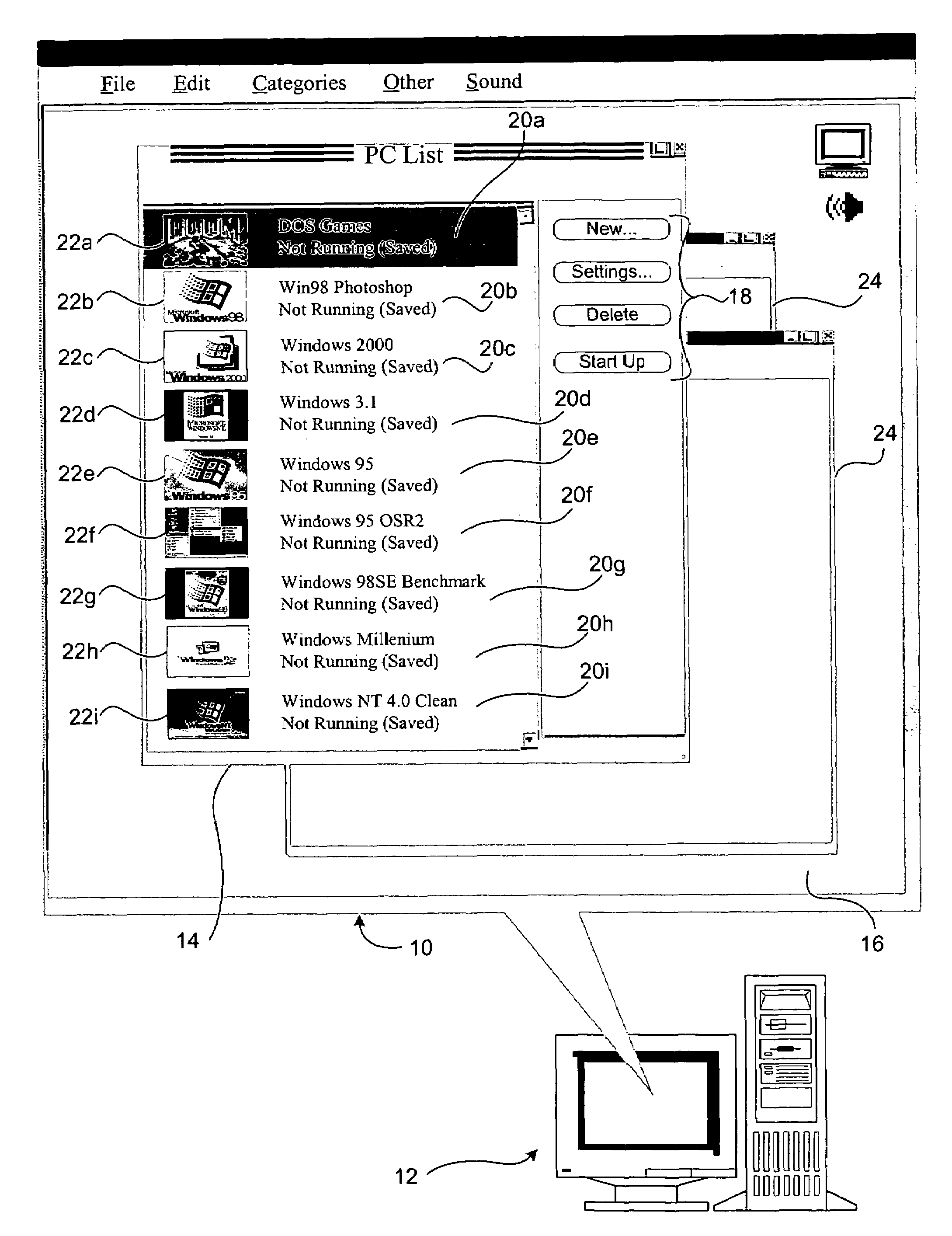
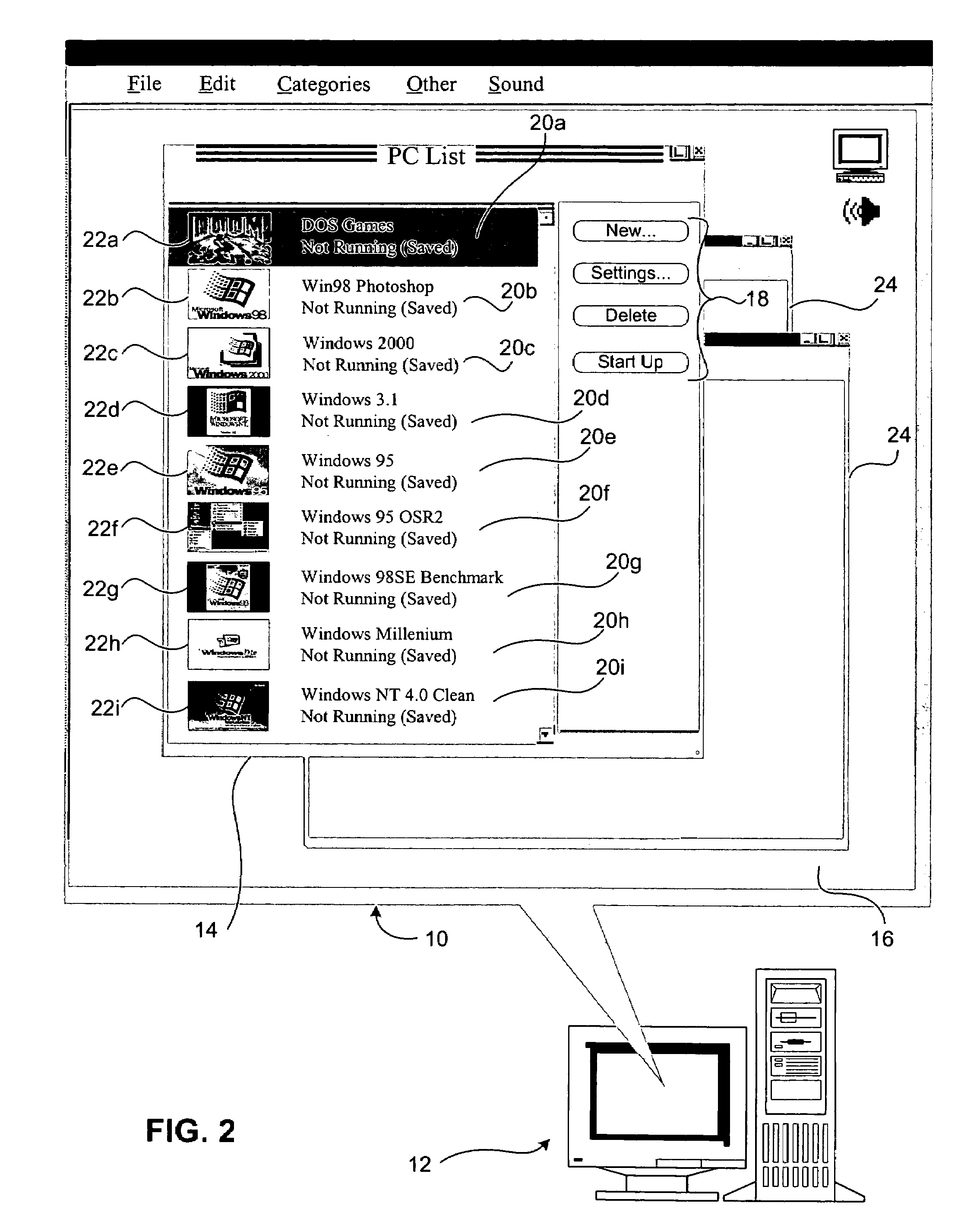
[0010]The system and method described herein allow a user of a host computer system running multiple virtual machine environments to view the thumbnail images of the video output of each virtual machine application. According to one embodiment of the present invention, the thumbnail images are generated by interpreting the contents of the virtual machine's video RAM (VRAM) and scaling the resulting representations into several thumbnail images that may be conveniently viewed, for example, in a single window. Interpretation of the virtual machine's VRAM is generally dependent on the current video mode of the virtual machine, such as text, planar video, linear video, among other examples. According to one embodiment of the present invention, the thumbnail images are generated using bilinear sampling techniques to create an anti-aliased miniature image. In the case of active emulated computer systems, thumbnail images are preferably continuously generated to give a real-time representation of the virtual machine application within the thumbnail view. The thumbnail or reduced-size images are preferably saved whenever the respective virtual machine is placed in a suspension mode and accordingly saved to the storage device of the computer system running the virtual machine software. The image of these suspended images are likewise displayed for the user, allowing the user to quickly view the status of the virtual machine regardless of whether the virtual machine is active or suspended.
[0011]The disclosed system and method provide several technical advantages over conventional systems and methods for managing multiple computer applications, such as multiple virtual computer environments. One advantage of the system and method of the present invention is that it allows a user of a computer system that is running multiple virtual machine environments to view the status of several multiple virtual machine environments at one glance. This allows the user to easily manage several virtual machine environments that are running simultaneously. Another advantage of the present system and method is that the user may quickly ascertain the status of a given virtual machine without having to activate or unsuspend the virtual machine. This allows the user to save time, especially if the virtual machine is running at a relatively slow speed, or if the user is working on several projects.

Problems solved by technology

As an example, the instruction set used by the Intel 80X86 processor family is incompatible with the instruction set used by the PowerPC processor family.
CISC processors use a large number of instructions, some of which can perform rather complicated functions, but which require generally many clock cycles to execute.
The uniqueness of the processor family among computer systems also typically results in incompatibility among the other elements of hardware architecture of the computer systems.
As the user increases the number of software applications and operating systems that is running on a computer system, it becomes more difficult for the user to manage the various tasks performed on the computer system.
Accordingly, as the user increases the number of virtual machines running on the computer system, it becomes more difficult for the user to keep track of both the virtual machines and the respective applications running on the computer system's native operating system and the various virtual machines.
Unfortunately, these application bars or lists generally do not present the user with enough information about the particular applications contained therein to allow the user to quickly find the particular application the user is interested in resuming.
This problem is exacerbated as the number of applications and corresponding windows increases.

Method used


Image

  • System and method for displaying images of virtual machine environments
  • System and method for displaying images of virtual machine environments
  • System and method for displaying images of virtual machine environments

Examples


Embodiment Construction

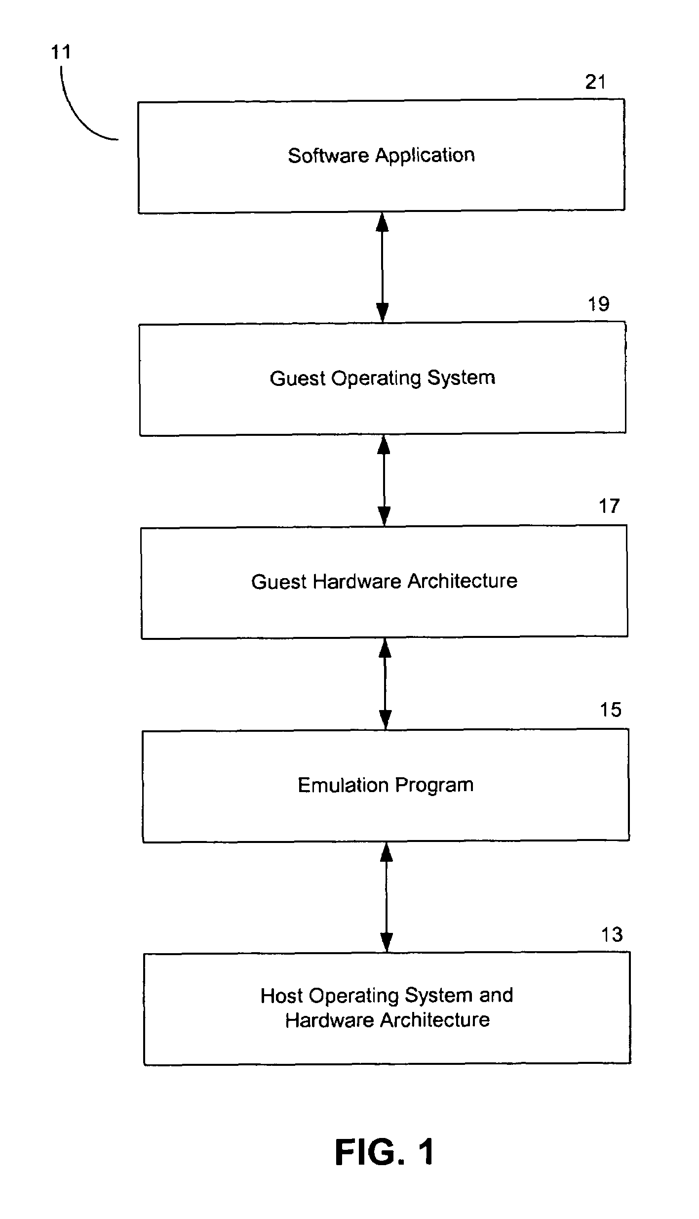
[0018]Shown in FIG. 1 is a diagram of the logical layers of the hardware and software architecture for an emulated operating environment in a computer system 11. An emulation program 15 runs on a host operating system and / or hardware architecture 13. Emulation program 15 emulates a guest hardware architecture 16 and a guest operating system 19. Software application 21 in turn runs on guest operating system 19. In the emulated operating environment of FIG. 1, because of the operation of emulation program 15, software application 21 can run on the computer system 11 even though software application 21 is designed to run on an operating system that is generally incompatible with the host operating system and hardware architecture 13.

[0019]Shown in FIG. 2 is a screen display 10 from a computer system 12 that implements the system and method of the present invention. Computer system 12 may use any type of processor and any type of operating system that are suitable for running one or mor...


PUM


Abstract

A system and method for displaying thumbnail images of the video output of one or more software applications in a window or similar graphical interface to allow the user of a computer system to conveniently and quickly monitor the overall status and progress of several software applications that are running simultaneously. The thumbnail images are generated from the VRAM associated with the software application and are preferably displayed with information corresponding to the associated software application. The thumbnail images may be static or generated at regular intervals according to user preference and the status of the software application.

Description

TECHNICAL FIELD OF THE INVENTION[0001]The present disclosure relates in general to the field of virtual machines, and, more particularly, to a system and method for displaying images from virtual machine environments.BACKGROUND OF THE INVENTION[0002]Computers include general purpose central processing units (CPUs) that are designed to execute a specific set of system instructions. A group of processors that have similar architecture or design specifications may be considered to be members of the same processor family. Examples of current processor families include the Motorola 680×0 processor family, manufactured by Motorola, Inc. of Phoenix, Ariz.; the Intel 80×86 processor family, manufactured by Intel Corporation of Sunnyvale, Calif.; and the PowerPC processor family, which is manufactured by Motorola, Inc. and used in computers manufactured by Apple Computer, Inc. of Cupertino, Calif. Although a group of processors may be in the same family because of their similar architecture ...

Claims


Application Information

Patent Timeline
IPC IPC(8): G06F3/048G06F9/44G06F9/455
CPCG06F9/4443G06F9/45537G06F9/451
Inventor TRAUT, ERIC P.MARTZ, BENJAMIN
Owner MICROSOFT TECH LICENSING LLC
Learn More