
Apparatus and method for measurement for dynamic laser signals

a laser signal and apparatus technology, applied in the direction of electrical apparatus, laser details, semiconductor lasers, etc., can solve the problems of extinction ratio and an increased bit error rate, signal strength to be reduced, and difficulty in obtaining feedback information

Inactive Publication Date: 2009-03-17
OL SECURITY LIABILITY CO +1
View PDF0 Cites 16 Cited by
  • Summary
  • Abstract
  • Description
  • Claims
  • Application Information

AI Technical Summary

Benefits of technology

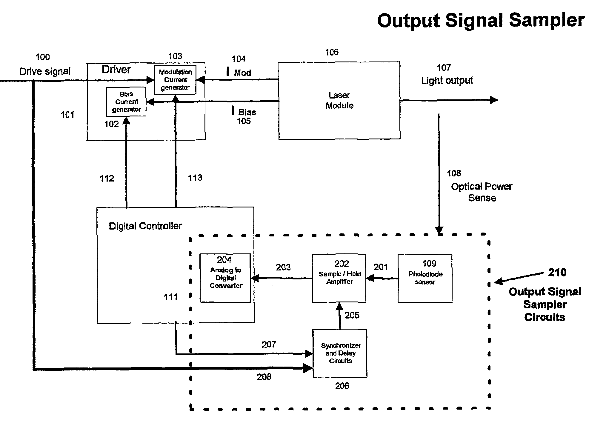
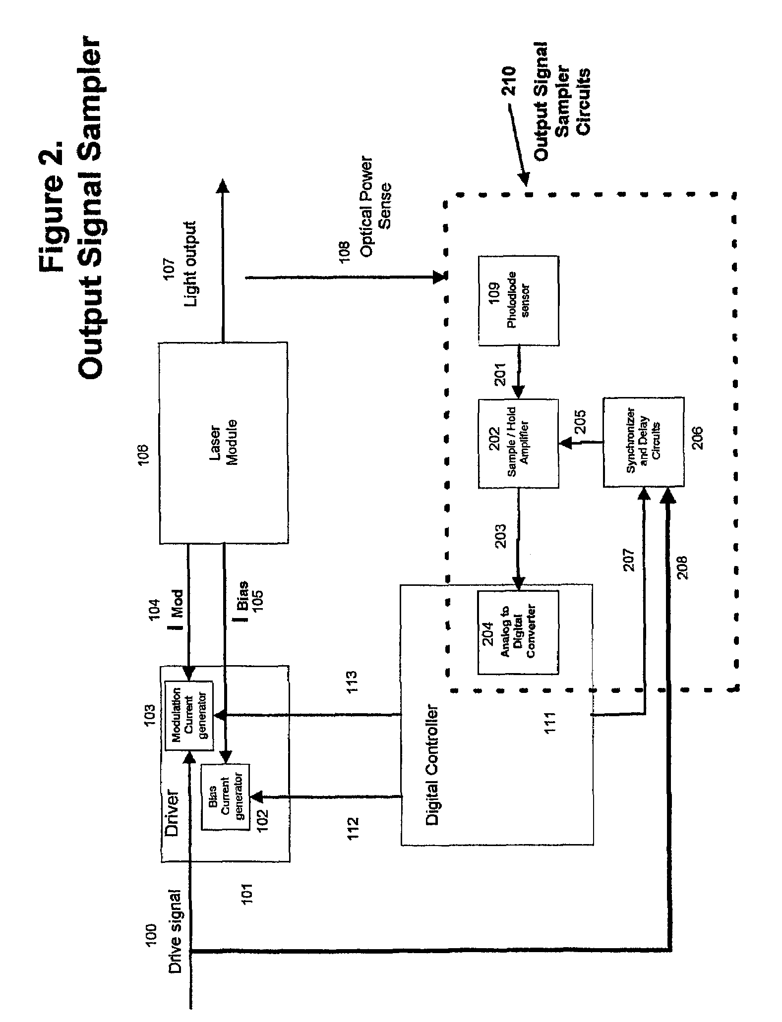
[0030]The present system contains a laser output measurement circuit used in a laser control system (114). The circuits contain a photodiode sensor (200), sample and hold amplifier (202), IC with synchronizer and delay circuits (206), and an analog to digital converter (204). The circuits measure the laser light output (107) while the laser Module (106) transmits signals. The measurement circuit tracks and stores the laser light output (107) signal using a Photodiode Sensor (109) and with a Sample / hold (202). The methods calculate the value of the laser light output (107) from mathematical relationships, which correlate the light output (107) of the laser Module (106) to the current value of the drive signal (100). Some of the distinguishing features in the present invention are 1) feedback information from the photodiode is obtained in a synchronous manner as a snapshot of the laser performance, and 2) the measurements are precise and calibrated, and 3) no disruption of the signal transmission occurs.
[0031]An advantage of this invention is that laser power amplitude can be calibrated without interrupting the flow of information transmission.
[0032]Another advantage of this invention is that the system can utilize multiple types of output responses from the Photodiode Sensor with the utilization of the appropriate correlation algorithm.
[0033]Another advantage of this invention is that the transmitter optical power can be continuously maintained at the optimal value to achieve the target Extinction Ratio, Bit Error Rate and analog signal level.
[0034]Another advantage of this invention is that the laser can be compensated for degradation due to aging.
[0035]Yet another advantage of this invention is that adjustments to account for temperature changes, aging and other effects are done only as needed and by the amount needed. This contributes to extending the life of the laser.

Problems solved by technology

This degradation causes the signal strength to be reduced resulting in a decrease of signal-to-noise ratio, extinction ratio and an increased Bit Error Rate.
When the control system is operational, obtaining feedback information becomes problematic since the light output (107) constantly changes depending on the Drive Signal (100) the system is transmitting.
Thus any attempts to measure the light output (107) will encounter errors, which can render the feedback information unusable.
This procedure disrupts the signal transmission and, because of this, the transmitter cannot send information over the optical communications channel while the calibration is carried out.
This approach has the disadvantage of requiring disconnection of the laser control system (114).
Disconnection in many systems, such as communications equipment, is not acceptable.
The problem with this solution is that it affects the information transmitted.
This prior art solution has a significant impact on the reliability of information transmission because it essentially inserts noise into the transmitted signal.
Furthermore this approach increases complexity and cost due to an additional calibration signal generator, a calibration signal injection circuit, plus filter and detection circuits.
Because of errors in power measurement, transmission systems in prior art generally overdrive the laser to account for variations of temperature, aging and other effects.
This approach significantly reduces the life of the laser.

Method used


Image

  • Apparatus and method for measurement for dynamic laser signals
  • Apparatus and method for measurement for dynamic laser signals
  • Apparatus and method for measurement for dynamic laser signals

Examples


Embodiment Construction

[0044]The above-mentioned difficulties and problems of the prior art are overcome by the present invention.

Apparatus

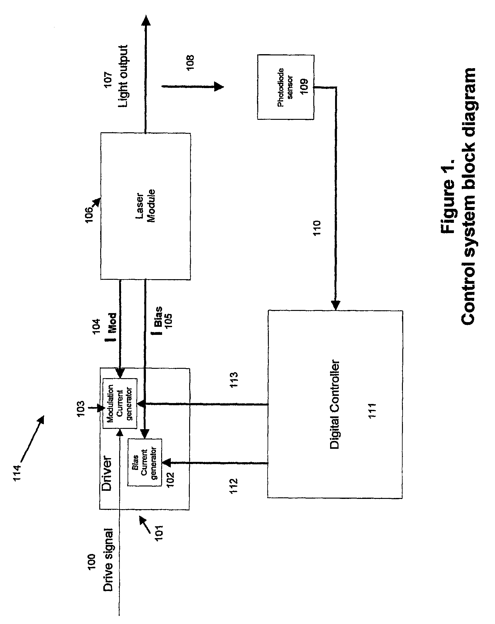
[0045]Referring to FIG. 1, a block diagram is shown for a Laser Control System (114). The system consists of a drive Signal Input (100) applied to a Laser Module Driver (101), which contains a Bias Current Generator (102) and a Modulation Current Generator (103). A Bias Control Signal (112) and a Modulation Control Signal (113) control the current generators. The Driver (101) produces Modulation Current (104) and Bias Current (105) that are applied to the Laser Module (106). The Laser Module (106) in turn produces Light Output (107). The magnitude of the Light Output (107) bears a relationship to the magnitude of the Modulation Current (104) and the Bias Current (105). A portion of the Light Output (107) from the laser is sensed. This portion constitutes the Optical Power Sense (108), which is coupled to a Photodiode Sensor (109). The Photodiode Sensor Output (110) is ...


PUM


Abstract

A system contains a laser output measurement circuit used in a laser control system (210). The circuits contain a photodiode sensor (109), sample and hold amplifier (202), IC with synchronizer and delay circuits (206), and an analog to digital converter (204). The circuits measure the laser light output (107) while the laser Module (106) transmits signals. The measurement circuit tracks and stores the laser light output (107) signal using a Photodiode Sensor (109) and with a Sample / hold (202). The methods calculate the value of the laser light output (107) from mathematical relationships, which correlate the light output (107) of the laser Module (106) to the current value of the drive signal (100). Some of the distinguishing features in the present invention are 1) feedback information from the photodiode is obtained in a synchronous manner as a snapshot of the laser performance, and 2) the measurements are precise and calibrated, and 3) no disruption of the signal transmission occurs.

Description

CROSS-REFERENCE TO RELATED APPLICATIONS[0001]This application is a National Stage of PCT / US2003 / 000463, filed Jan. 8, 2003, which claims the benefit of U.S. Provisional Application No. 60 / 346,728, filed Jan. 8, 2002.BACKGROUND[0002]1. Field of the Invention[0003]The present invention relates to a circuit and method used to calibrate and compensate for laser performance in systems such as an optical communications links, medical diagnostic systems and any other system utilizing lasers. Performance compensation is achieved in a non-invasive manner without disruption of the laser signal transmission or other operating parameters of the laser.[0004]2. Description of the Related Art[0005]Market trends demand increased levels of reliability and intelligence in laser systems. Particularly, in laser signal transmission there is the need to send information with reliable optical power signals. Reliability requires the transmitted signals to maintain a given signal strength as well as other p...

Claims


Application Information

Patent Timeline
Patent Type & Authority Patents(United States)
IPC IPC(8): H01S3/00H01S5/042H01S5/068H01S5/0683H04B10/08H04B10/155
CPCH01S5/06832H01S5/06835H04B10/077H04B10/07955H04B10/504H04B10/564H01S5/042H01S5/06808H01S5/06812H01S5/06825
Inventor SANCHEZ, JORGE
Owner OL SECURITY LIABILITY CO
Learn More