Connector assembly for allowing relative movement between two building members

a technology of connecting parts and connecting parts, which is applied in the direction of girders, shock-proofing, manufacturing tools, etc., can solve the problems of injury and death, and unfavorable movement in a horizontal plan

Active Publication Date: 2009-03-17
THE STEEL NETWORK
View PDF43 Cites 66 Cited by
  • Summary
  • Abstract
  • Description
  • Claims
  • Application Information

AI Technical Summary

Problems solved by technology

Seismic activity plagues buildings and their inhabitants in many areas of the world, causing untold amounts of damage and monetary loss in addition to injury and loss of life.
Building damage is mainly due to the vibration of a building which causes shifts of one portion of the building frame with respect to another portion.
In conventional construction, the building components are rigidly locked together and their connective joints will fracture under the vibrational stress, often resulting in collapse.
However, none of these patents provides for movement in a horizontal plane, although this movement does occur during an earthquake.
Thus, while the building floor is free to move relative to its walls for a limited vertical distance when the known connectors are used, horizontal movement is not an option.
When the seismic vibration occurs in a direction to induce horizontal shift, damage, injury, and death can still happen.

Method used


Image

  • Connector assembly for allowing relative movement between two building members
  • Connector assembly for allowing relative movement between two building members
  • Connector assembly for allowing relative movement between two building members

Examples


Embodiment Construction

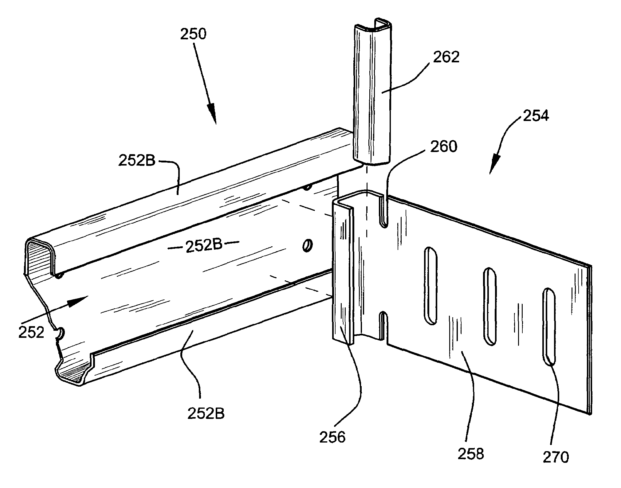
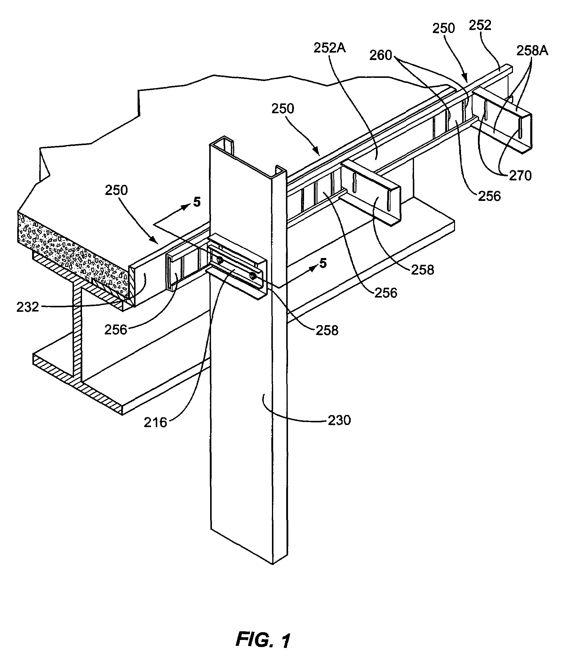
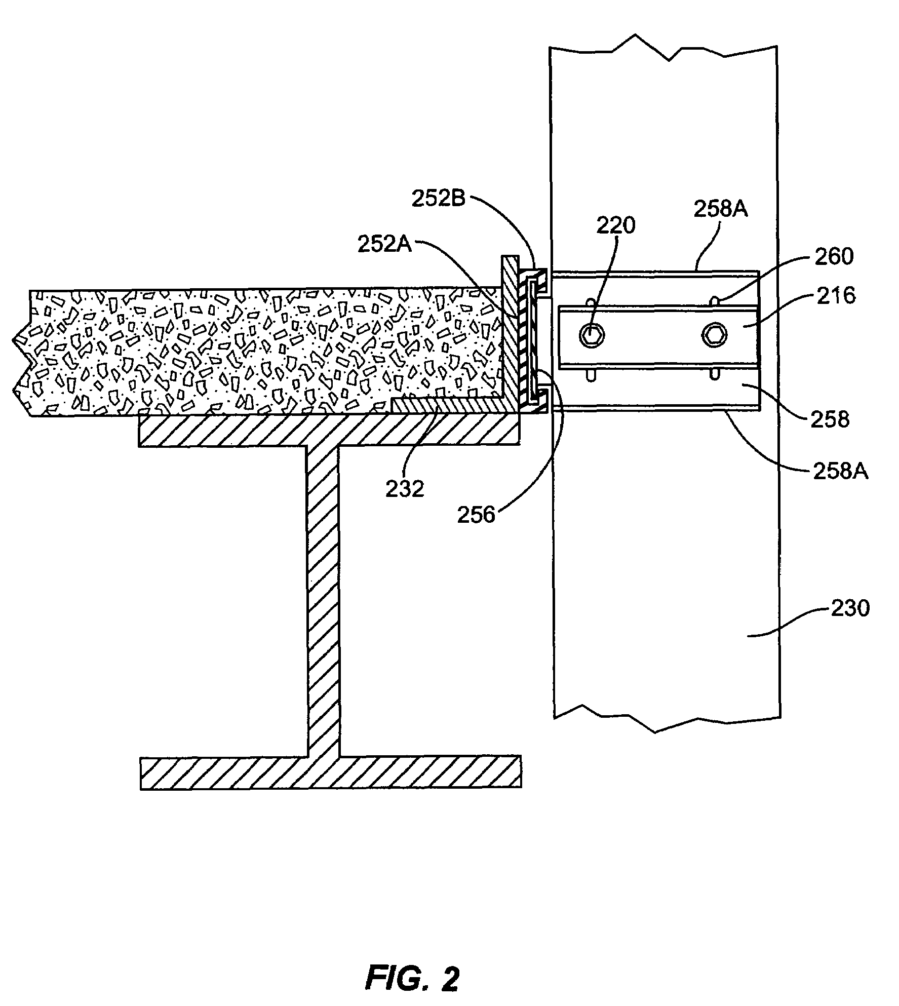
[0016]With further reference to the drawings, particularly FIGS. 1 and 2, a connector assembly is shown and indicated generally by the numeral 250. Connector assembly 250 is connected between a first member 232 which in this case is a horizontal member that forms a part of a floor structure and a second member 230 that in this case is a vertical member and a stud. As will be appreciated from subsequent portions of this disclosure, when the connector assembly 250 is connected between the first and second members 230, 232 bidirectional movement is permitted between the first and second members.

[0017]Connector assembly 250 includes an elongated track 252 that in this case is secured to the first member 232. Elongated track 252 is generally C-shaped and includes a back or web 252A and opposed outer edge portions 252B. Outer edge portions 252B form a channel. This is particularly illustrated in FIG. 2.

[0018]Slidably mounted or contained within track 252 is a connecting member indicated g...


PUM


Abstract

A connector assembly for a building structure is provided. The connector assembly includes an elongated track that is mounted to a first member of a building frame structure. A connecting member is connected to the elongated track and retained within a pair of opposed channels that form a part of the track. Connected to the connecting member is a second member of the building frame structure. Formed in the connecting member is at least one elongated slot that permits the connecting member to be connected to the second member and for there to be relative movement between the connecting member and the second member. Further, the connecting member is slidable back and forth within the elongated track. Thus, it is appreciated that bidirectional movement between the first and second members can be accommodated by the connecting member sliding back and forth along the track on one hand and by there being relative movement about the connection between the connecting member and the second member.

Description

CROSS REFERENCE TO RELATED APPLICATION[0001]This is continuation-in-part of U.S. patent application Ser. No. 10 / 689,498 filed Oct. 20, 2003 now U.S. Pat. No. 7,104,024. The disclosure of this application is expressly incorporated herein by reference.FIELD OF THE INVENTION[0002]The present invention relates to light steel framing and more particularly, to a connector for connecting two structural members together in a manner that will allow one of the members to move relative to the other member.BACKGROUND OF THE INVENTION[0003]Seismic activity plagues buildings and their inhabitants in many areas of the world, causing untold amounts of damage and monetary loss in addition to injury and loss of life. Building damage is mainly due to the vibration of a building which causes shifts of one portion of the building frame with respect to another portion. In conventional construction, the building components are rigidly locked together and their connective joints will fracture under the vib...

Claims


Application Information

Patent Timeline
Patent Type & Authority Patents(United States)
IPC IPC(8): E04C3/04
CPCE04B2/96Y10T403/73F16B2200/67
Inventor DIGIROLAMO, EDWARD R.TORRES, MICHAELBENNETT, GARYBOOTH, MICHAEL
Owner THE STEEL NETWORK
Why Eureka
Try Eureka