
Optical disk apparatus

a technology of optical disk and optical disk, applied in the field of optical disk apparatus, can solve the problems of lowering the level of lpp signal, difficult to extract lpp signal correctly, mark affecting lpp, etc., and achieve the effect of suppressing omission of lpp and detection of synchronization information error

Inactive Publication Date: 2009-03-10
TEAC CORP
View PDF10 Cites 0 Cited by
  • Summary
  • Abstract
  • Description
  • Claims
  • Application Information

AI Technical Summary

Benefits of technology

The present invention provides an optical disk apparatus that can reliably detect and address land pre-pits on an optical disk when recording and playing data. This is achieved by setting the synchronization information of consecutive frames in a way that minimizes the impact of land pre-pits on the synchronization information of the i-th frame. The synchronization information of the i-th frame and the (i+1)th frame is set to a space, while the synchronization information of the (i+2)th frame is set to the opposite polarity of the synchronization information of the i-th frame. This ensures that the synchronization information of either the i-th frame or the (i+2)th frame is a space when the i-th frame is an even frame, and likewise when the i-th frame is an odd frame. This allows for reliable ROPC at the timing of a mark and ensures that the synchronization information of one of two frames always remains a space.

Problems solved by technology

It is therefore difficult to extract an LPP signal correctly when a fixed threshold value is used for binarization.
When the mark is selected as the synchronization information, however, problems arise that such a mark affects LPP at the time of recording the mark and that LPP is affected by the mark when reproducing the LPP.
When a laser power which is modulated is irradiated onto an optical disk so as to record synchronization information using a mark having a length of 14T at the position of the LPP, however, in the process of forming a mark having a length 14T by irradiation of the laser power, heat is diffused to the adjacent land, which may cause deformation of the LPP in the adjacent land, thereby lowering the LPP signal level.
In addition, as a mark portion having a length of 14T forms a pit, the reflectively of this portion itself is also decreased, which further makes it difficult to extract an LPP signal from a reproduction signal.
Similar problems arise when reproducing data which has been recorded.
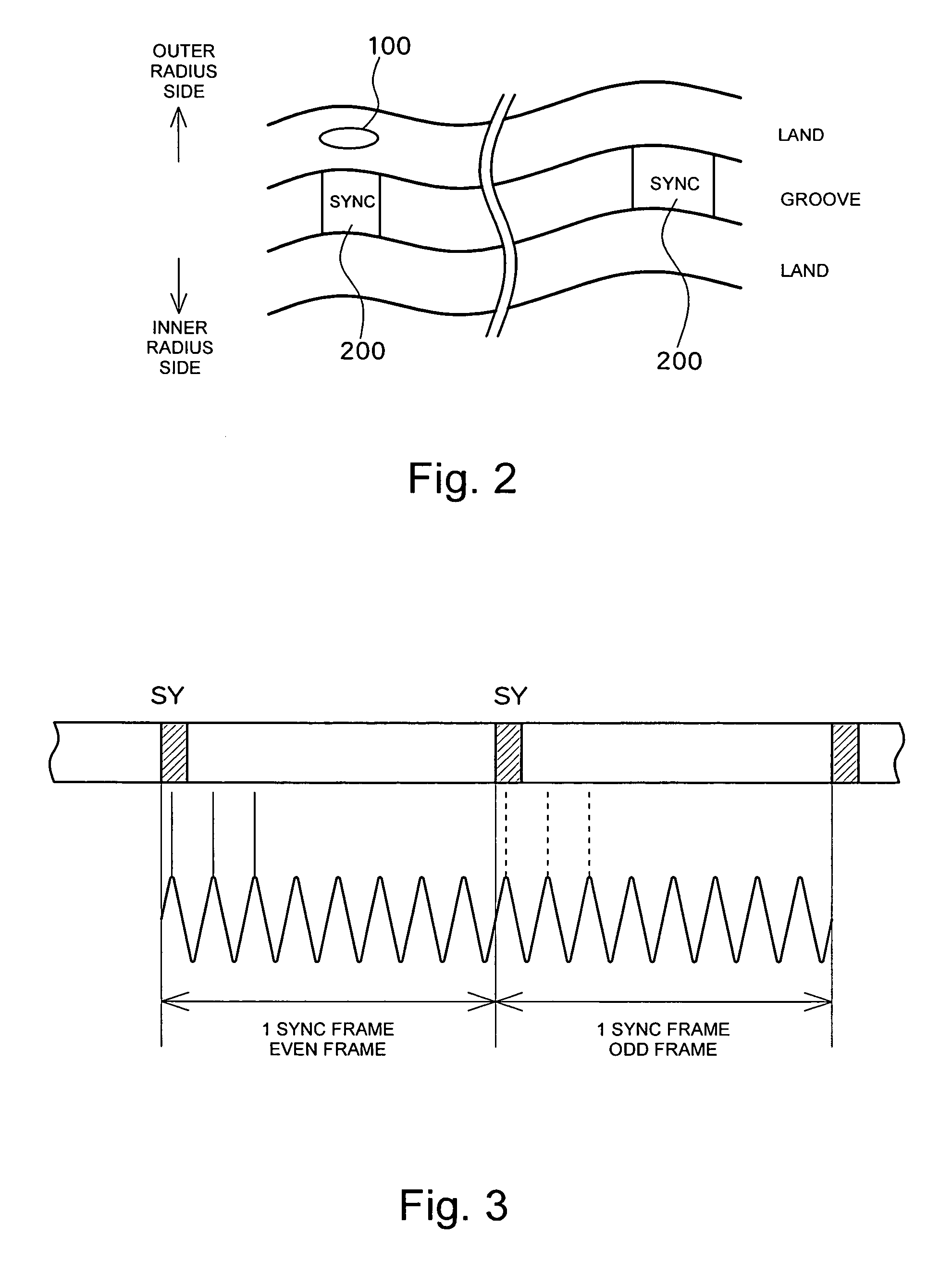
Specifically, as the synchronization information having a length of 14T and LPP exist at the synchronized position, an LPP signal is included in the 14T portion of a reproduced signal, which may cause an error in detecting the synchronization information of 14T.
With this technology, while it is possible to prevent effects of the marks on the LPP by controlling such that the synchronization information of the even frames are always set to spaces when the LPP is formed at the top of even frames, this cannot provide a satisfactory solution because the LPP may be disposed in the odd frames.

Method used


Image

  • Optical disk apparatus
  • Optical disk apparatus
  • Optical disk apparatus

Examples


first embodiment

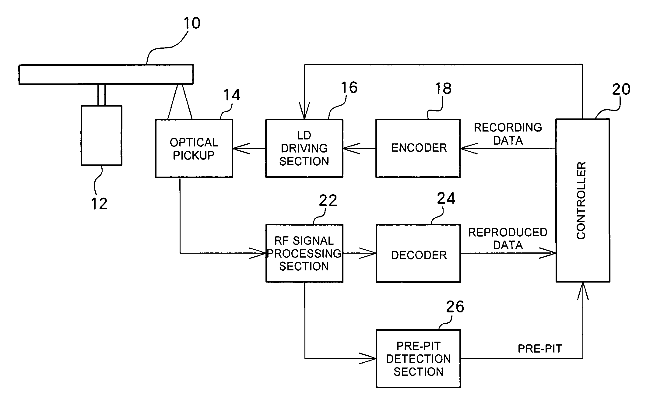
[0032]FIG. 1 shows a block diagram of a structure of an optical disk apparatus according to an embodiment of the present invention. An optical disk (DVD-R) is driven by a spindle motor 12 to rotate at CAV (or CLV). Pre-pits (land pre-pits) are formed at a predetermined interval in an area (a land) between grooves which are information recording tracks of the optical disk 10. The position within the plane of the optical disk 10 can be specified by detecting the pre-pits.

[0033]An optical pickup 14, which is disposed opposing the optical disk 10, irradiates laser light of a recording power onto the optical disk 10 for recording data and irradiates laser light of a reproducing power for reproducing recorded data. At the time of recording, recording data supplied from a controller 20 is modulated by an encoder 18 and the modulated data is further converted into a driving signal by an LD driving section 16 for driving a laser diode (LD) of the optical pickup 15. At the time of data reprod...

second embodiment

[0058]FIG. 7 shows a flowchart of another process in the SYNC selection section 18g in the encoder 18. In this embodiment, four consecutive frames constitute one unit, in which the synchronization information of the first of the four consecutive frames is set based on the DSV value and the synchronization information items of the remaining frames are then set based on the polarity of the synchronization information of the first frame.

[0059]First, the frame number i is initialized to 0 (S201), and the polarity of the i-th synchronization information is set such that DSV is minimized (S202). Consequently, the 14T synchronization information of the 0th frame is set to a space, for example. Then, with regard to the (i+1)th synchronization information, the polarity is set opposite to that of the i-th synchronization information (S203). Thus, the 14T synchronization information of the first frame is set to a mark, for example. Then, the polarity of the (i+2)th synchronization information ...

third embodiment

[0067]FIG. 9 shows a flowchart of still another process in the SYNC selection section 18g in the encoder 18. In this embodiment, four consecutive frames constitute one unit, in which the synchronization information item of the first of the four consecutive frames is set based on the DSV value and the synchronization information items of the remaining frames are then set based on the polarity of the synchronization information of the first frame.

[0068]First, the frame number i is initialized to 0 (S301), and the polarity of the i-th synchronization information is set such that DSV is minimized (S302). Consequently, the 14T synchronization information of the 0th frame is set to a space, for example. Then, the (i+1)th synchronization information is set to the same polarity as that of the i-th synchronization information (S303). Thus, the 14T synchronization information of the 1st frame is set to a space, for example. Then, the polarity of the (i+2)th synchronization information is set ...


PUM

PropertyMeasurementUnit
polarityaaaaaaaaaa
areaaaaaaaaaaa
areasaaaaaaaaaa

Abstract

An optical disk apparatus for recording data on an optical disk having a land pre-pit (LPP). An encoder of a DVD-R / RW drive records data while inserting synchronization information having a length of 14T at the top of a synchronous frame. The encoder sets synchronization information of the i-th frame (wherein i is an integer which is 0 or greater) and the (i+1)th frame of a plurality of consecutive frames to either a mark or a space such that each DSV is minimized. The encoder sets the synchronization information of the (i+2)th frame such that the polarity of the synchronization information of the (i+2)th frame is opposite to the polarity of the synchronization information of the i-th frame, and sets the synchronization information of (i+3)th frame such that the polarity of the synchronization information of (i+3)th frame is opposite to the polarity of the synchronization information of the (i+1)th frame. In this manner, the synchronization information of one of two frames, whether they are two odd frames or two even frames, is always set to a space.

Description

BACKGROUND OF THE INVENTION[0001]1. Field of the Invention[0002]The present invention relates to an optical disk apparatus, and more particularly to an apparatus which performs data recording / reproducing with respect to an optical disk having a pre-pit.[0003]2. Description of Related Art[0004]Optical disk apparatuses such as DVD-R drives and DVD-RW drives demodulate address information which is previously formed on an optical disk for determining the address, and perform data recording / reproducing. The address information is formed in such a manner that the address information is embedded by wobbling the tracks, and also in such a manner that pre-pits are formed in lands adjacent to grooves which are information recording tracks. Here, in DVD-RAMs in which both lands and grooves are information recording tracks, the address information is embedded in an embossed portion of an area formed by the embossed portion and a data portion. The present application will be described in conside...

Claims


Application Information

Patent Timeline
Patent Type & Authority Patents(United States)
IPC IPC(8): G11B5/09
CPCG11B20/1403G11B2020/1287
Inventor MASHIMO, AKIRA
Owner TEAC CORP
Learn More