Digital transmission system and clock reproducing device
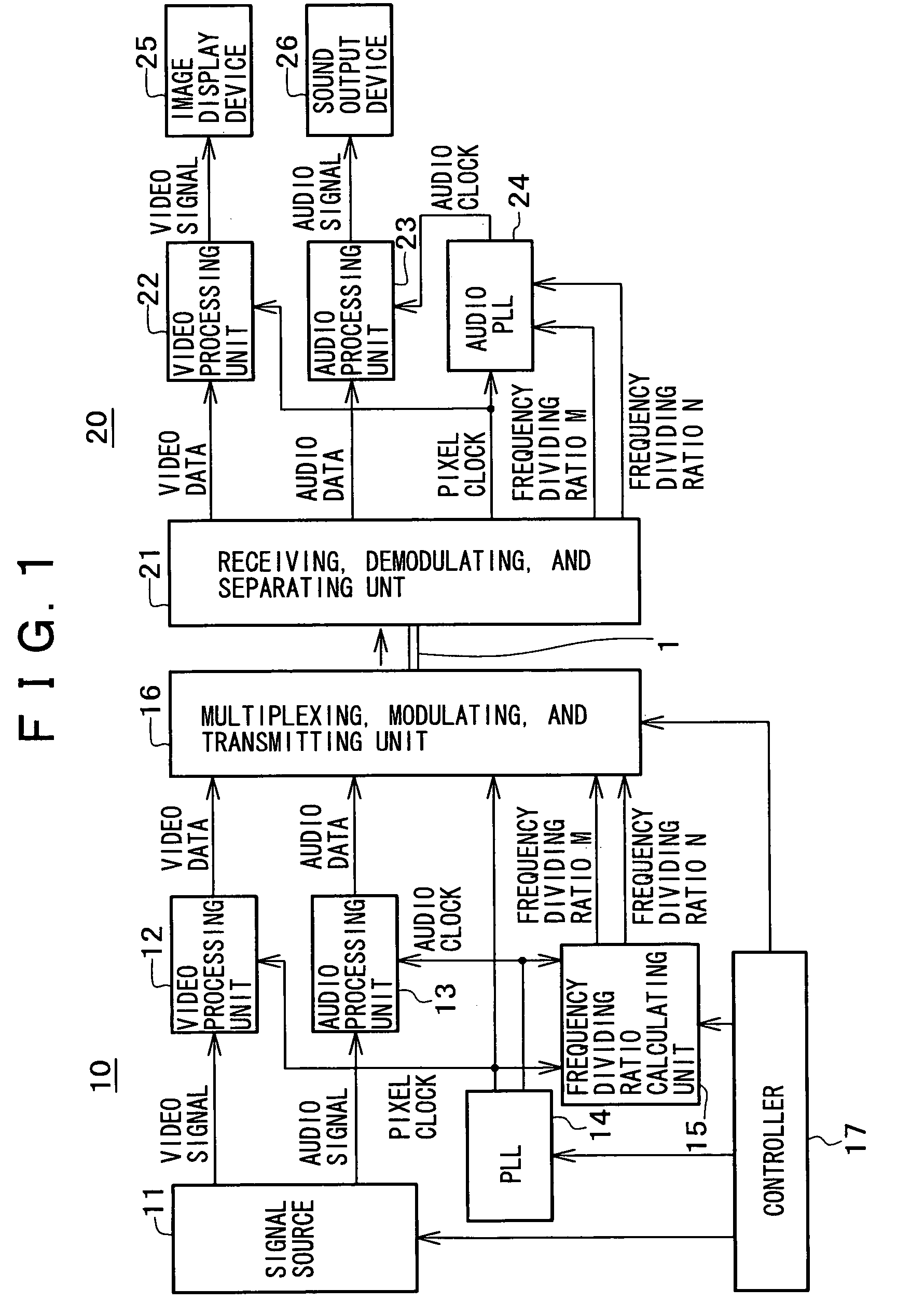
a transmission system and clock technology, applied in the field of digital transmission systems, can solve the problems of complicated transmission system configuration, inability to change the vco oscillation frequency range immediately on the receiving side, and complicated configuration of the transmission system
- Summary
- Abstract
- Description
- Claims
- Application Information
AI Technical Summary
Benefits of technology
Problems solved by technology
Method used
Image
Examples
first example
FIG. 2 and FIG. 3
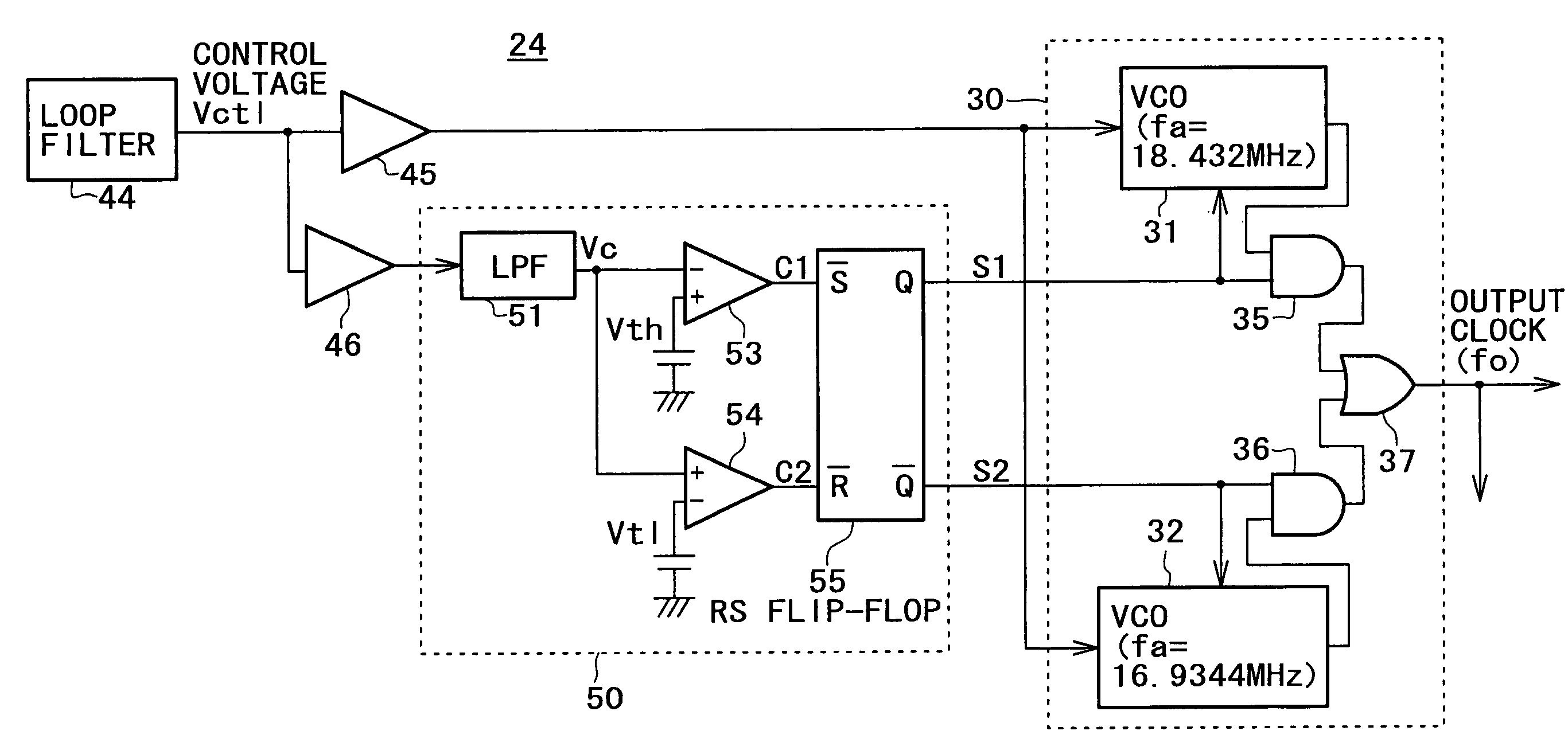
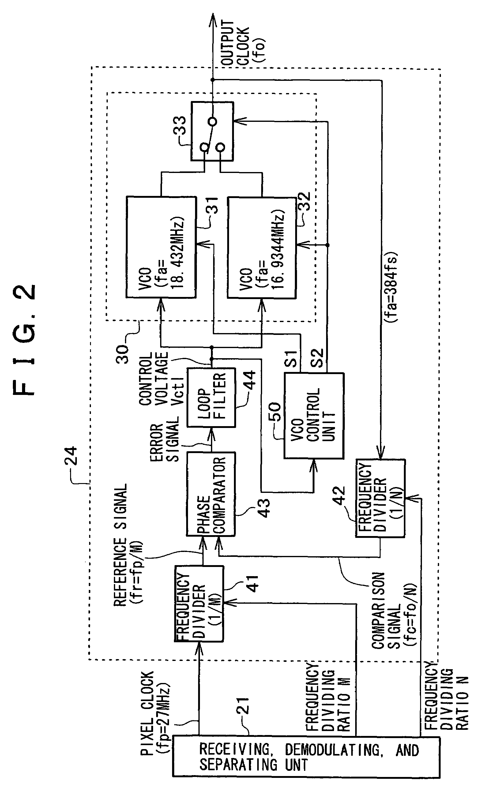
[0038]FIG. 2 shows a first example of the audio PLL 24.
[0039]The audio PLL 24 in this example includes a switching selector circuit 33 and two VCOs 31 and 32 as an oscillating unit 30 so as to deal with the audio sampling frequency fs switched to 48 kHz and 44.1 kHz on the transmitting side 10 as described above.
[0040]The VCO 31 provides an audio clock of a frequency fa=384 fs of 18.432 MHz. The VCO 32 provides an audio clock of a frequency fa=384 fs of 16.9344 MHz. Each of the VCOs 31 and 32 has a narrow oscillation frequency range so as to ensure a certain jitter performance, and has a characteristic of linearly increasing the oscillation frequency as an input control voltage Vctl is increased.
[0041]The audio PLL 24 comprises such an oscillating unit 30, frequency dividers 41 and 42, a phase comparator 43, a loop filter 44, and a VCO control unit 50.
[0042]The frequency divider 41 divides the frequency fp=27 MHz of the pixel clock by M, and thereby provides a refer...
second example
FIG. 4
[0064]While the VCO control unit 50 in the example of FIG. 2 and FIG. 3 detects a change in the audio sampling frequency fs from the control voltage Vctl as the output of the loop filter 44, that is, the error signal as the output of the phase comparator 43, and changes the oscillation frequency range of the oscillating unit 30, the VCO control unit 50 may be configured to detect a change in the audio sampling frequency fs from the oscillation frequency of the oscillating unit 30, that is, the frequency fo of the output clock of the oscillating unit 30, and change the oscillation frequency range of the oscillating unit 30.
[0065]FIG. 4 shows an example in this case. A VCO control unit 50 in this example comprises a frequency discriminator circuit 56, two comparators 57 and 58, and a state retaining RS flip-flop 55.
[0066]The frequency discriminator circuit 56 discriminates the frequency fo of the output clock of the oscillating unit 30. The frequency discriminator circuit 56 pro...
PUM
| Property | Measurement | Unit |
|---|---|---|
| frequency fa | aaaaa | aaaaa |
| frequency fa | aaaaa | aaaaa |
| frequency fa | aaaaa | aaaaa |
Abstract
Description
Claims
Application Information
 - R&D
- Intellectual Property
- Life Sciences
- Materials
- Tech Scout
- Unparalleled Data Quality
- Higher Quality Content
- 60% Fewer Hallucinations
Browse by: Latest US Patents, China's latest patents, Technical Efficacy Thesaurus, Application Domain, Technology Topic, Popular Technical Reports.
© 2025 PatSnap. All rights reserved.Legal|Privacy policy|Modern Slavery Act Transparency Statement|Sitemap|About US| Contact US: help@patsnap.com


