
Multipurpose sensor port

a sensor port and multi-purpose technology, applied in the field of physiological instruments, can solve the problems of non-standard protocol and processor interface, and lack of communication ports

Active Publication Date: 2009-03-10
JPMORGAN CHASE BANK NA
View PDF101 Cites 767 Cited by
  • Summary
  • Abstract
  • Description
  • Claims
  • Application Information

AI Technical Summary

Benefits of technology

"The patent text describes a method for updating the firmware in a pulse oximeter by using a sensor port and a data source, such as a PC or nonvolatile memory. This allows for easy field upgrades of all instruments without hardware modification. The sensor port can be connected to an analog sensor or a data source, and the data can be used to download firmware or processed as a physiological measurement. The system can also include a drive path for transmitting optical radiation and receiving a detector response, as well as a memory for storing data and instructions for the signal processor. The technical effects of this patent include improved firmware updates and flexibility in data sources for downloading and processing."

Problems solved by technology

Some of the protocols and processor interfaces are non-standard, requiring custom programming for different instruments.
This is particularly problematic when the instruments are part of an installed base at various medical facilities.
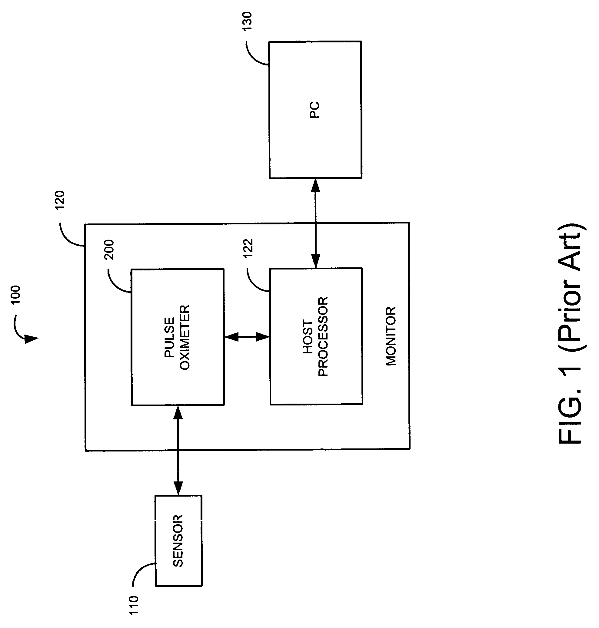
Further, some pulse oximeter products, such as handheld products, may not have a communications port for connecting to an external computer, and firmware upgrades would typically require returning the instrument to the factory.

Method used


Image

  • Multipurpose sensor port
  • Multipurpose sensor port
  • Multipurpose sensor port

Examples


embodiment 301

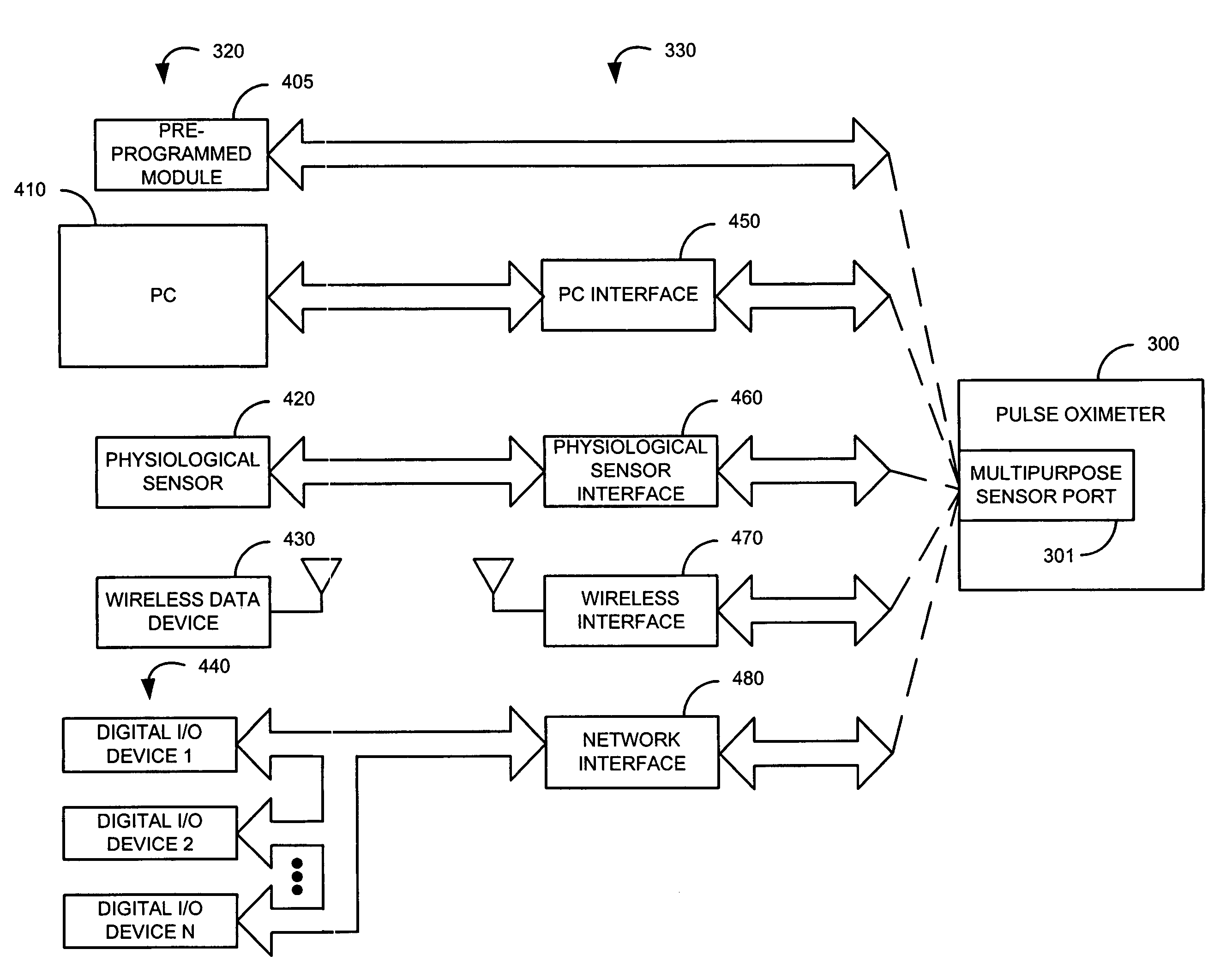
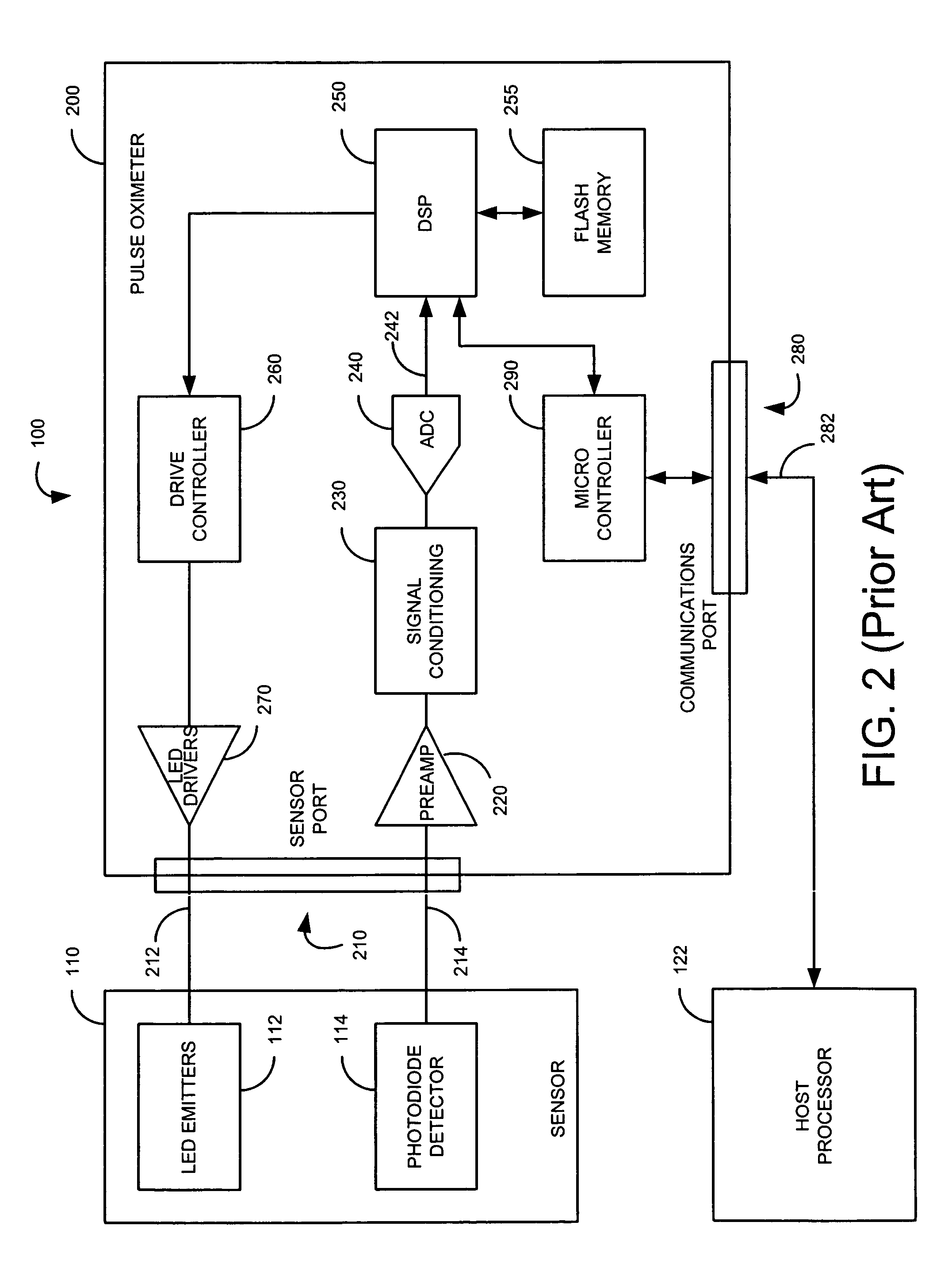
[0035]FIG. 7 illustrates a multipurpose sensor port embodiment 301 incorporating an LED drive path 510, a detector signal path 520 and a DSP 530, which function generally as described with respect to FIG. 5, above. The LED drive path 510 has a shift register 710, a red LED drive 720 and an IR LED drive 730. The shift register 710 has a data input 712, a red control output 714 and an IR control output 718. The DSP 530 provides serial control data on the shift register input 712 that is latched to the shift register outputs 714, 718 so as to turn on and off the LED drives 720, 730 according to a predetermined sequence of red on, IR on and dark periods. The detector signal path 520 has a preamp 740, signal conditioning 750 and an ADC 760 that perform amplification, filtering and digitization of the detector signal 522. The detector signal path 520 also has a comparator 770 that compares the preamp output 742 to a fixed voltage level and provides an interrupt output 774 to the DSP 530 a...

embodiment 450

[0037]FIG. 9 illustrates an RS-232 PC interface embodiment 450 having an RS-232 connector 910, a sensor connector 920, a voltage regulator 930 and a transceiver 940. The voltage regulator 930 draws power from either the RS-232 910 RTS (request to send) or DTR (data terminal ready) signal lines and provides regulated VCC power to transceiver 940. The transceiver 940 operates on either of the sensor 920 red or IR drive signal lines to generate an RS-232 910 RXD (receive data) signal. The transceiver 940 further operates on the RS-232 TXD (transmit data) signal line to generate a sensor 920 detector signal.


PUM


Abstract

A sensor port is adapted to connect to either a sensor or a data source. A reader is configured to identify which of the sensor and the data source is connected to the sensor port. A data path is configured to communicate an analog signal associated with the sensor and digital data associated with the data source to a signal processor according to the identification made by the reader.

Description

REFERENCE TO RELATED APPLICATIONS[0001]The present application claims benefit of U.S. Provisional Application No. 60 / 490,091 filed Jul. 25, 2003, entitled “Multipurpose Sensor Port.” The present application incorporates the disclosure of the foregoing application herein by reference.BACKGROUND OF THE INVENTION[0002]A pulse oximeter is a physiological instrument that provides noninvasive measurements of arterial oxygen saturation along with pulse rate. To make these measurements, a pulse oximeter performs a spectral analysis of the pulsatile component of arterial blood so as to determine the relative concentration of oxygenated hemoglobin, the major oxygen carrying constituent of blood. Pulse oximeters provide early detection of decreases in the arterial oxygen supply, reducing the risk of accidental death and injury. As a result, these instruments have gained rapid acceptance in a wide variety of medical applications, including surgical wards, intensive care units, general wards and...

Claims


Application Information

Patent Timeline
Patent Type & Authority Patents(United States)
IPC IPC(8): A61B5/145A61B5/00A61B5/024G06F19/00
CPCA61B5/0002A61B5/02416A61B5/14551G06F19/3406A61B2560/045A61B2562/08G16H40/63A61B5/14552G05B19/02
Inventor AL-ALI, AMMARSMITH, ROBERT AMCCARTHY, REX J.
Owner JPMORGAN CHASE BANK NA
Learn More