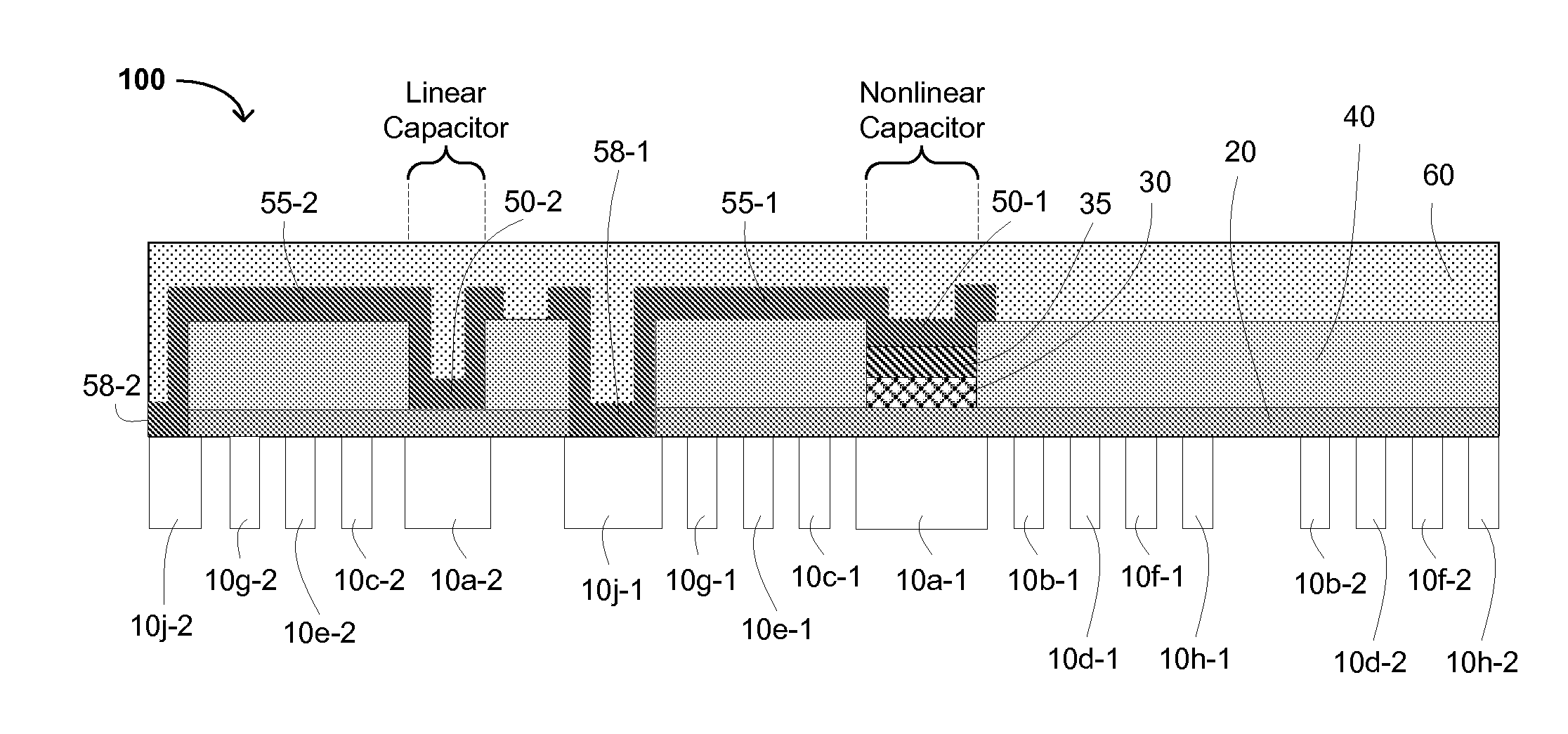

Electronic article surveillance (EAS) tag/device with coplanar and/or multiple coil circuits, an EAS tag/device with two or more memory bits, and methods for tuning the resonant frequency of an RLC EAS tag/device

a technology of eas and eas tags, which is applied in the direction of burglar alarms, mechanical actuation of burglar alarms, instruments, etc., can solve the problems of limiting the read range, difficult and costly to hold tight tolerances on capacitors, and difficult to manufacture two rlc circuits using pre-existing eas and/or rfid tags. , to achieve the effect of low cost and increased detection rang

Active Publication Date: 2009-03-03
ENSURGE MICROPOWER ASA
View PDF38 Cites 25 Cited by
  • Summary
  • Abstract
  • Description
  • Claims
  • Application Information

AI Technical Summary

Benefits of technology

"The present invention is about an electronic article surveillance (EAS) tag / device with coplanar and / or multiple coil circuits, and methods for making the tag / device. The device has increased detection range, more than one bit of write-once memory capability, and resonant frequency tuning capability after assembly. The method includes depositing semiconductor material or precursor on a thin dielectric film, forming conductive structures for electrical communication, and etching the substrate to form the inductors. The invention provides a low-cost EAS, RF, and RFID tag with these advanced features."

Problems solved by technology

This is particularly problematic for RF tags designed to generate frequency division signals so as to divide a broadcast or carrier frequency.
Further, Federal Communications Commission (FCC) regulations on the amount of RF field that can be broadcast by a tag reader also limit the read range, a key specification parameter for an RF EAS or RFID system.
Generally speaking, the cost to manufacture two RLC circuits using pre-existing EAS and / or RFID tag technology is twice that of a single circuit.
Also, it is generally very difficult and costly to hold tight tolerances on the capacitor in an RLC resonant circuit of an RF electronic surveillance tag during a low cost manufacturing process.
One challenge to allowing reduced tolerances in low cost EAS tag manufacturing lies in matching the resonant frequency of an RLC circuit to a fixed frequency of an RF reader system, such as may be installed at the exit of a store or library, for example.

Method used


Image

  • Electronic article surveillance (EAS) tag/device with coplanar and/or multiple coil circuits, an EAS tag/device with two or more memory bits, and methods for tuning the resonant frequency of an RLC EAS tag/device
  • Electronic article surveillance (EAS) tag/device with coplanar and/or multiple coil circuits, an EAS tag/device with two or more memory bits, and methods for tuning the resonant frequency of an RLC EAS tag/device
  • Electronic article surveillance (EAS) tag/device with coplanar and/or multiple coil circuits, an EAS tag/device with two or more memory bits, and methods for tuning the resonant frequency of an RLC EAS tag/device

Examples


Embodiment Construction

[0037]Reference will now be made in detail to the preferred embodiments of the invention, examples of which are illustrated in the accompanying drawings. While the invention will be described in conjunction with the preferred embodiments, it will be understood that they are not intended to limit the invention to these embodiments. On the contrary, the invention is intended to cover alternatives, modifications and equivalents, which may be included within the spirit and scope of the invention as defined by the appended claims. Furthermore, in the following detailed description of the present invention, numerous specific details are set forth in order to provide a thorough understanding of the present invention. However, it will be readily apparent to one skilled in the art that the present invention may be practiced without these specific details. In other instances, well-known methods, procedures, components, and circuits have not been described in detail so as not to unnecessarily ...


PUM


Abstract

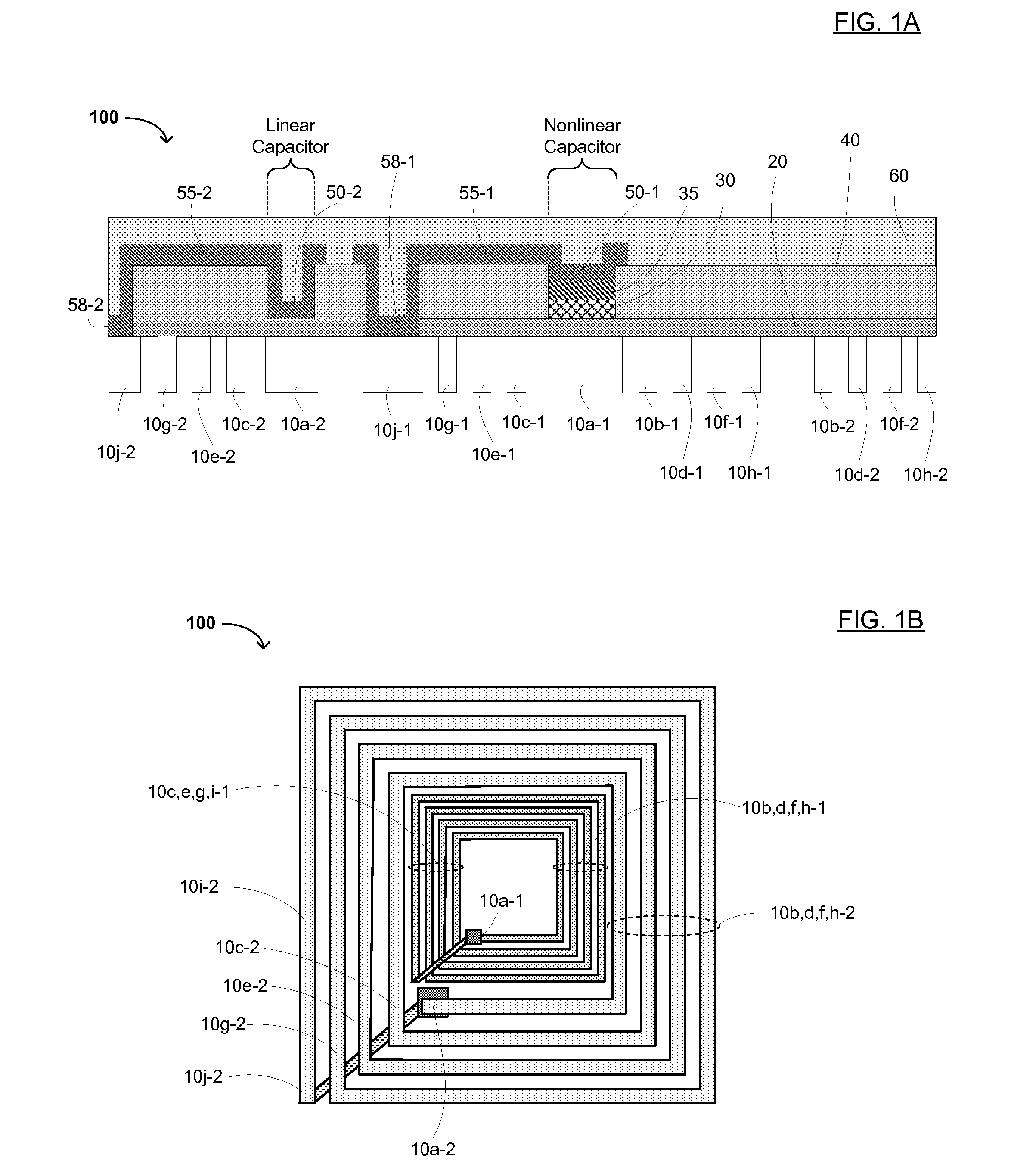
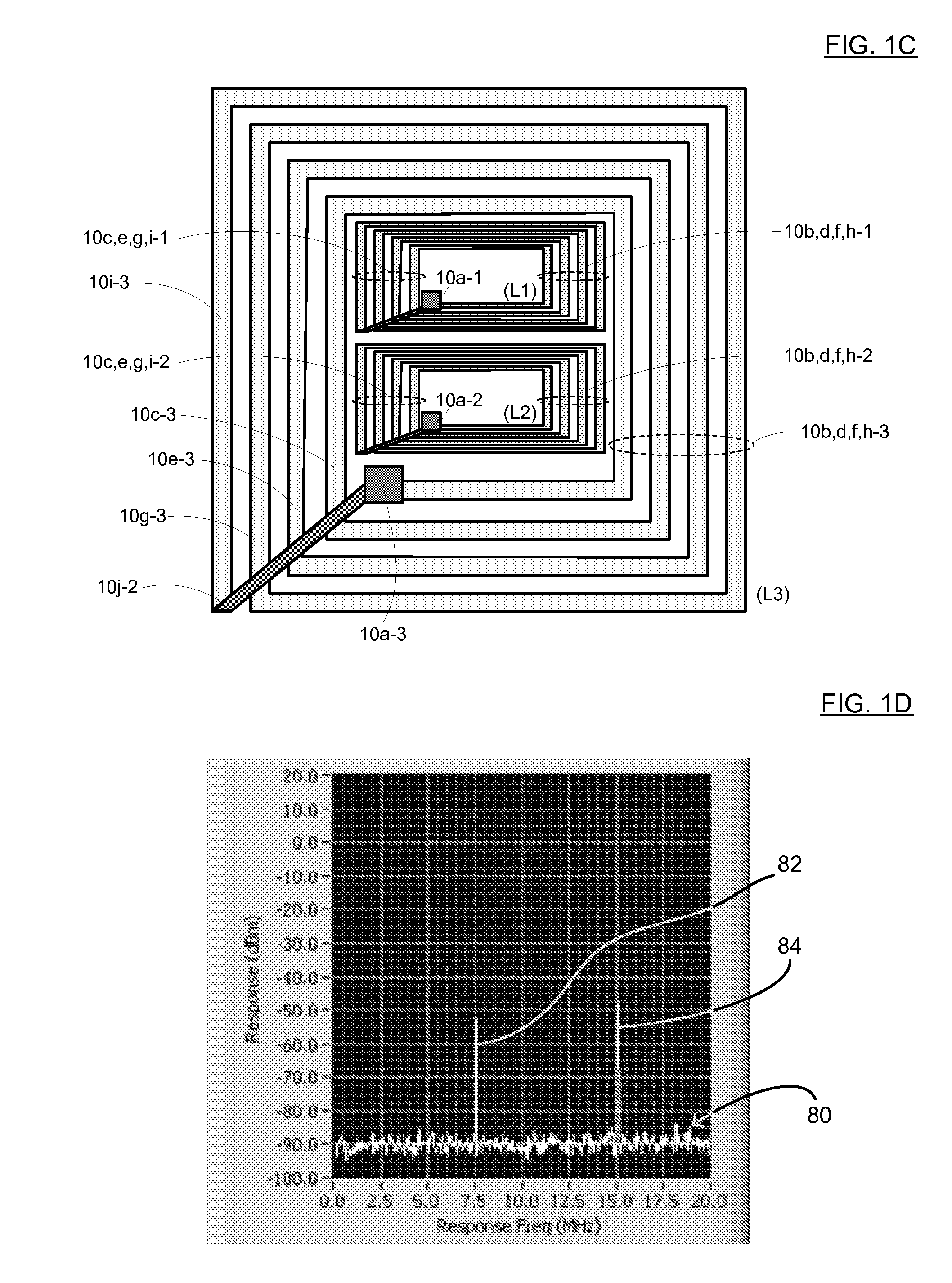
An EAS device, and methods for making the device for tuning the resonant frequency of the same is disclosed. The EAS device includes: an outer inductor having one end coupled to a linear or nonlinear capacitor plate; an inner inductor having one end coupled to the other type of capacitor; a first dielectric film on the outer and inner inductors and the capacitor plates coupled thereto, having openings exposing other ends of the outer and inner inductors; a second linear capacitor plate on the dielectric film; a second nonlinear capacitor plate on the dielectric film; a second dielectric film containing holes for the second linear and nonlinear capacitor plates, and exposing the other ends of the first and second inductors; and first and second conducting straps on the second dielectric film, configured to electrically connect one of the exposed inductor ends to a corresponding second capacitor plate.

Description

RELATED APPLICATIONS[0001]This application is a continuation of U.S. patent application Ser. No. 11 / 104,375, filed Apr. 11, 2005 now U.S. Pat. No. 7,286,053, which claims the benefit of U.S. Provisional Application No. 60 / 592,596, filed Jul. 31, 2004, which is incorporated herein by reference in its entirety.FIELD OF THE INVENTION[0002]The present invention generally relates to the field of electronic article surveillance (EAS), radio frequency (RF) and / or RF identification (RFID) tags and devices. More specifically, embodiments of the present invention pertain to EAS tags with coplanar and / or multiple coil circuits, EAS tags with two or more memory bits, and methods for tuning the resonant frequency of an RLC EAS tag.DISCUSSION OF THE BACKGROUND[0003]The detection range of an electronic article surveillance (EAS) tag that is based on resonant resistor-inductor-capacitor (RLC) circuits is limited by the magnetic flux that is available at the coil or inductor of the tag from the read...

Claims


Application Information

Patent Timeline
Patent Type & Authority Patents(United States)
IPC IPC(8): G08B13/14
CPCG08B13/2414G08B13/2417G08B13/242G08B13/2437G08B13/2448
Inventor GUDEMAN, CHRISTOPHERMACKENZIE, J. DEVINCLEEVES, J. MONTAGUEARREOLA, JOSE
Owner ENSURGE MICROPOWER ASA
Learn More