
Sliding bearing and method for the manufacture thereof

a technology of sliding bearings and sliding faces, which is applied in the direction of non-disconnectible pipe joints, adjustable joints, shearing machines, etc., can solve the problems of inability to consider the grinding of slide faces for corresponding fit, lack of accurate guidance, etc., and achieve the effect of low cos

Inactive Publication Date: 2009-03-03
SUSPA
View PDF20 Cites 6 Cited by
  • Summary
  • Abstract
  • Description
  • Claims
  • Application Information

AI Technical Summary

Benefits of technology

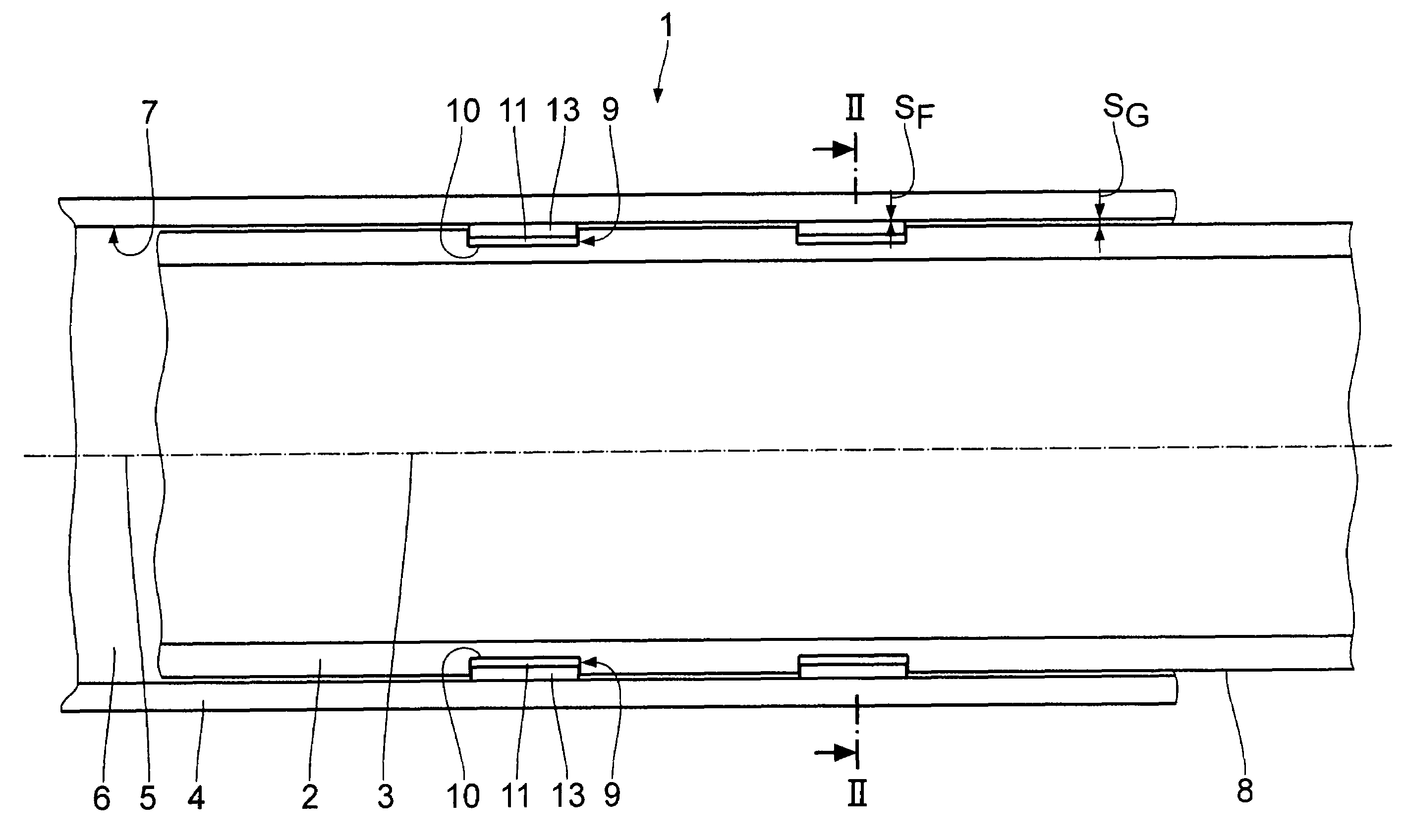
The present invention provides a sliding bearing that is cost-effective and overcomes prior art drawbacks. The sliding bearing comprises a second bearing member with a bearing recess and a first bearing member that is inserted into the recess and mounted axially or radially. A sliding / guiding element is disposed between the first and second bearing members for guidance of motion. An equalizing compound is applied between the sliding / guiding element and the bearing member to adapt the guide clearance between the sliding / guiding element and the slide face. The sliding bearing is manufactured by a method that involves providing a second bearing member with a bearing recess and a first bearing member that is insertable in the recess. The equalizing compound is applied to the slide face and the sliding band is placed on top. The first bearing member is then inserted into the recess and the excess equalizing compound is squeezed into equalizing areas. The equalizing compound is curved. The technical effect of the invention is that it provides a sliding element that can adapt to the associated slide face with accurate positioning, even at a low cost.

Problems solved by technology

Frequently, work tolerances are the reason for the lack of accurate guidance right from the start.
Grinding the slide faces for corresponding fit cannot be considered because of the cost factor.

Method used


Image

  • Sliding bearing and method for the manufacture thereof
  • Sliding bearing and method for the manufacture thereof
  • Sliding bearing and method for the manufacture thereof

Examples


Embodiment Construction

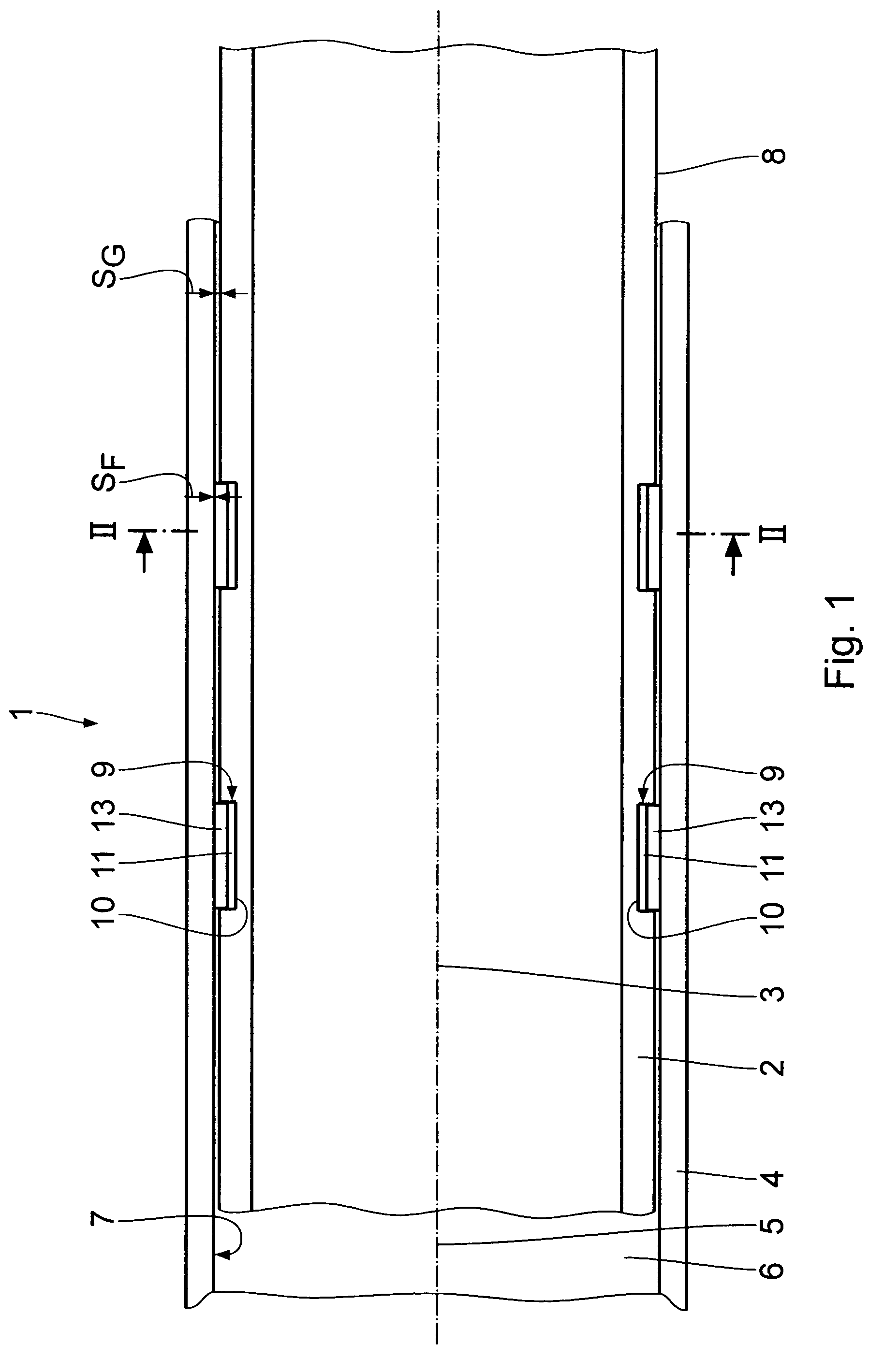
[0017]The following is a description of a first embodiment of the invention, taken in conjunction with FIGS. 1 and 2. A sliding bearing 1 comprises an interior pipe 2 as a first bearing member, having an associated central longitudinal axis 3, and an exterior pipe 4 as a second bearing member, having an associated central longitudinal axis 5 which coincides with the axis 3. The sliding bearing 1 permits the interior pipe 2 to be axially and / or radially arranged in relation to the exterior pipe 4. The pipes 2 and 4 can be structural components of a telescopic unit of several pipes which are disposed successively one within the other and which are displaceable one relative to the other for example by a spindle drive.

[0018]The exterior pipe 4 encloses a cylindrical interior space 6, which is open at the ends, and it comprises a slide face 7 on its inside. The interior pipe 2, which is disposed in the exterior pipe 4 concentrically thereof, comprises a cylindrical slide face 8 on its ex...


PUM

PropertyMeasurementUnit
diameteraaaaaaaaaa
radial depthaaaaaaaaaa
adhesiveaaaaaaaaaa

Abstract

A sliding bearing for axial and / or radial arrangement of a first bearing member in relation to a second bearing member, comprises a second bearing member, which has a bearing recess provided with a second slide face; a first bearing member, which is lodged in the bearing recess and which is mounted axially and / or radially, the first bearing member having a first slide face, which is opposite the second slide face and spaced therefrom by a clearance; at least one sliding / guiding element, which is disposed between the first and the second bearing members and fixed in relation to one bearing member, for guidance of a motion of the first relative to the second bearing member; an equalizing compound, which is disposed between the at least one sliding / guiding element and the bearing member relative to which is fixed the at least one sliding / guiding element, for adaptation of the guide clearance between the at least one sliding / guiding element and the slide face that is displaceable in relation thereto, the equalizing compound being solid in the operating state of the sliding bearing and free-flowing prior thereto.

Description

BACKGROUND OF THE INVENTION[0001]1. Field of the Invention[0002]The invention relates to a sliding bearing for axial and / or radial arrangement of a first bearing member, in particular an interior pipe, in relation to a second bearing member, in particular an exterior pipe, as well as to a method of manufacturing the sliding bearing.[0003]2. Background Art[0004]In telescopic structures, several pipes of successively decreasing diameter are insertable one into the other. It is of great importance that the pipes be slidable substantially free from play, accurately guided along a single central longitudinal axis. Frequently, work tolerances are the reason for the lack of accurate guidance right from the start. Grinding the slide faces for corresponding fit cannot be considered because of the cost factor.SUMMARY OF THE INVENTION[0005]It is an object of the present invention to embody a sliding bearing at as low a cost as possible that will overcome the prior art drawbacks.[0006]This obje...

Claims


Application Information

Patent Timeline
Patent Type & Authority Patents(United States)
IPC IPC(8): A61M25/02B21D53/10B23D11/00B23D25/00B29D31/00F16C17/26F16C19/00F16C35/00F16C33/20B29D99/00F16C17/02F16C29/02F16C31/02F16C33/08F16C43/02F16M11/26
CPCF16C29/02F16C33/08F16M11/26F16M11/28F16C31/02Y10T403/7077F16M2200/027Y10T403/32467Y10T29/4984Y10T29/49885Y10T29/49641Y10T403/32213Y10T29/49705Y10T403/32524Y10T29/49679
Inventor MULLER, HERBERT
Owner SUSPA
Learn More