
Wide passband optical interleaver

a wide-passband, optical interleaver technology, applied in the field of optical interleavers, can solve the problems of high fabrication cost and inability to perfect the usb filter, and achieve the effect of wide-passband and greatly improved effective bandwidth ratio of the passband

Active Publication Date: 2009-02-24
IND TECH RES INST
View PDF6 Cites 6 Cited by
  • Summary
  • Abstract
  • Description
  • Claims
  • Application Information

AI Technical Summary

Benefits of technology

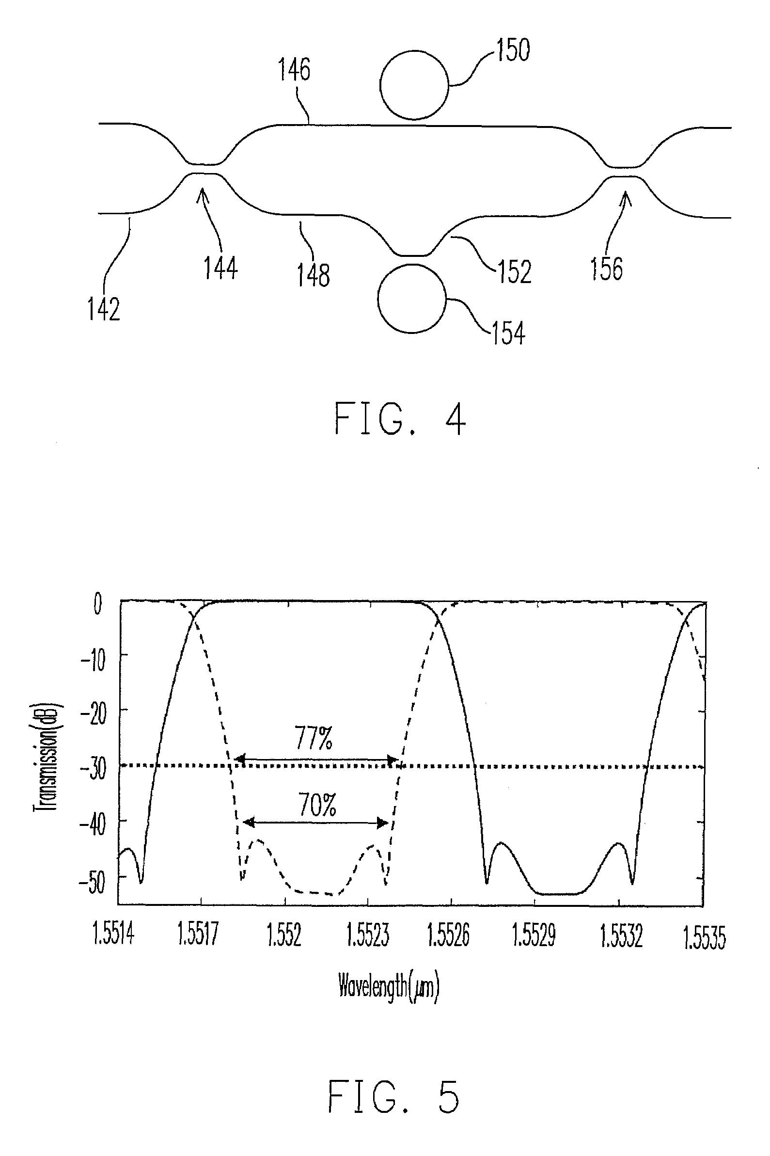
[0009]The present invention provides an optical interleaver with wide passband. The effective bandwidth ratio for the passband can be greatly improved.

Problems solved by technology

However, the usual filter is not in a perfect condition.
When the frequency band of the optical signal in a single wavelength becomes narrow, the system needs to be designed with high precision, or the optical signal is very easily operated at the range of stopband of the filter, resulting in signal error.
This also causes the high fabrication cost.

Method used


Image

  • Wide passband optical interleaver
  • Wide passband optical interleaver
  • Wide passband optical interleaver

Examples


Embodiment Construction

[0021]In the invention, the interleaver of the present invention can have wide passband, so that the signal error can be effectively reduced. Several embodiments are provided for descriptions but the present invention is not only limited to the embodiments.

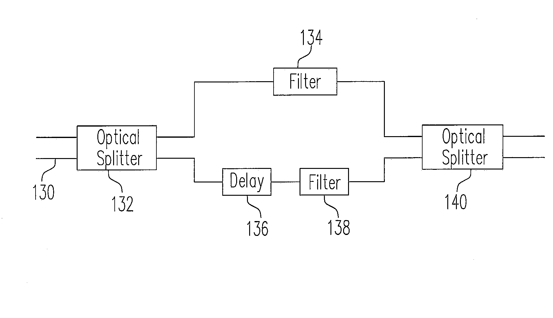
[0022]FIG. 3 is a drawing, schematically illustrating a functional structure of a wide passband interleaver, according to an embodiment of the present invention. In FIG. 3, the interleaver includes a MZI basic structure, having a delay 136, two optical filters 134 and 138, and another optical splitter 140. The MZI basic structure includes a first optical splitter 132, having two input terminals 130 and two output terminals. Basically, only one of the input terminals 130 is needed for actually Inputting a sequence of signals with different wavelengths. The input optical signal is split into two signals to the two output terminals. The two output terminals are then coupled to two optical routes, namely a first optical route and a se...


PUM


Abstract

A wide passband optical interleaver includes a first optical splitter, having a first output terminal and a second output terminal. A first optical route is coupled to the first output terminal. A second optical route is coupled to the second output terminal. A delay is coupled on the second optical route. A second optical splitter having two input terminals is receiving the first optical route and the second optical route. A plurality of optical filter respectively having transmission coefficients ρi is coupled to the first optical route and the second optical route. The transmission coefficients ρi are determined by satisfying a desired quantity of effective group delay ratio T, defined asT=∑i⁢Si⁢1-ρi1+ρi,where⁢⁢Si⁢⁢is+1⁢⁢or-1.where Si is +1 or −1.

Description

BACKGROUND OF THE INVENTION[0001]1. Field of Invention[0002]The present invention relates to optical interleaver. More particularly, the present invention relates to a wide passband interleaver.[0003]2. Description of Related Art[0004]The optical channel interleaver has been widely applied in a system or apparatus of Dense Wavelength-Division Multiplexing (DWDM), in which the DWDM technology is one of the best solutions to transmit a large amount of data. The interleaver and its application is shown in FIG. 1. In FIG. 1, the interleaver 100 receives a sequence of optical signals at the operation wavelengths, such as λ1, λ2, λ3, . . . λ79, λ80. The interleaver 100, for example, divides the 80 signals into an odd group of λ1, λ3, . . . λ79 and an even group λ2, λ4, . . . λ80. The signals of the odd group are output from one terminal while the signals of the even group are output from another terminal, in sequence. Basically, the signals of odd group are complementary to the signals of...

Claims


Application Information

Patent Timeline
Patent Type & Authority Patents(United States)
IPC IPC(8): G02B6/28
CPCG02B6/12007
Inventor CHANG, SHIH-JUNGHUANG, YIN-CHIEHNI, CHI-YUCHEN, YUNG-JUI
Owner IND TECH RES INST
Learn More