Mold clamping apparatus, injection molding machine and injection molding method
a technology of injection molding machine and clamping apparatus, which is applied in the direction of dough shaping, applications, manufacturing tools, etc., can solve the problems of affecting the mold exchange work, and leaking resin or forms on the molded objects, etc., to achieve simple and reliable construction, avoid obstructing the mold exchange work, and easy to retract
- Summary
- Abstract
- Description
- Claims
- Application Information
AI Technical Summary
Benefits of technology
Problems solved by technology
Method used
Image
Examples
first embodiment
of Mold Clamping Apparatus
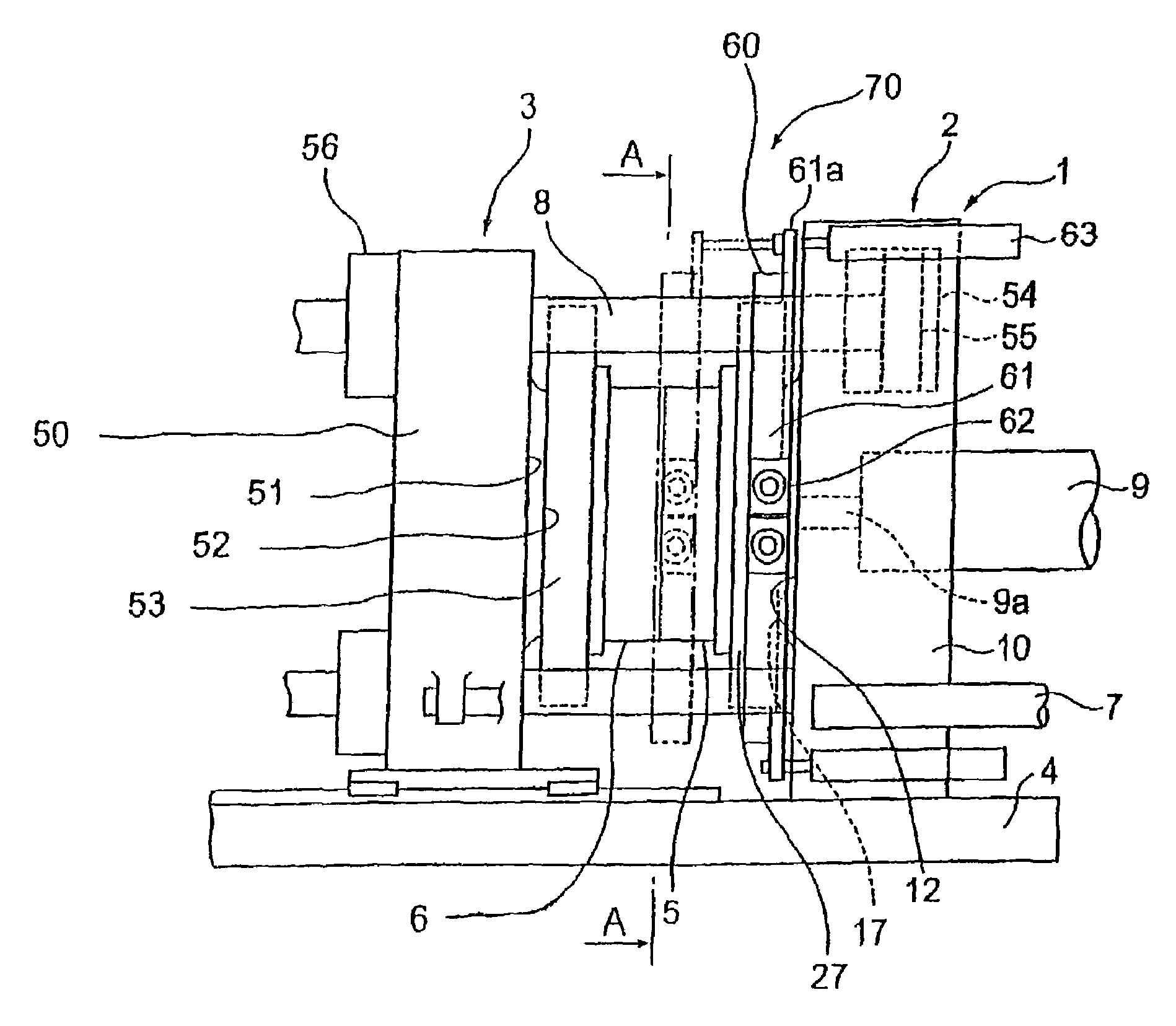
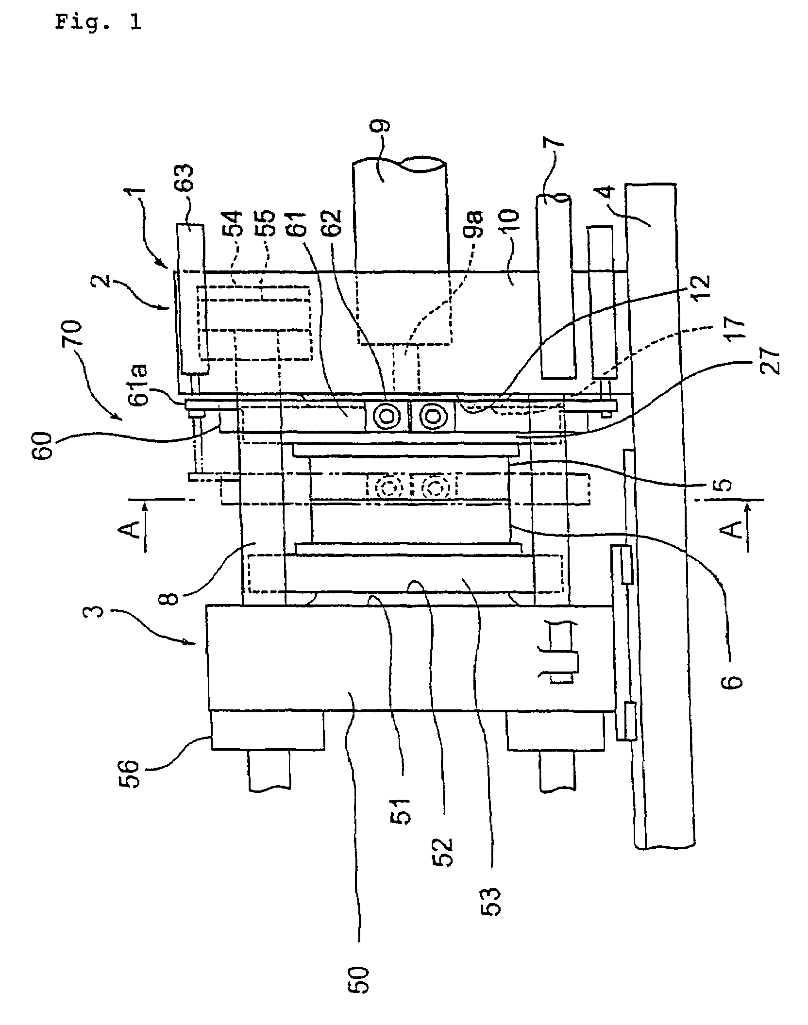
[0057]FIG. 1 is a side view showing a construction of related part of an injection molding machine comprising a first embodiment of a mold clamping apparatus according to the present invention. FIG. 2 is a cross sectional view taken on line A-A of FIG. 1.
[0058]In FIGS. 1 and 2, numeral 70 designates a mold clamping apparatus comprising a side pusher 60. A fixed platen 2 as a fixed die plate to which a fixed mold 5 is fitted is fixedly mounted on an injection unit 9 side on a base frame 4 of the injection molding machine. A movable platen 3 as a movable die plate to which a movable mold 6 is fitted is movably arranged along an axial direction of tie bars 8 (right and left directions in FIG. 1) on the base frame 4 by action of a moving cylinder 7, ball screw mechanism or the like. Also, the fixed platen 2 and movable platen 3 are constructed to be linkable to each other by the tie bars 8. A die plate 1 is thus constructed by these parts and components.
[0059]T...
second embodiment
of Mold Clamping Apparatus
[0077]A second embodiment of a mold clamping apparatus 90 comprising a side pusher 80, different from the side pusher 60, according to the present invention will be described with reference to FIGS. 3 to 5. FIG. 3 is a side view showing a construction of related part of an injection molding machine comprising the second embodiment of the mold clamping apparatus. FIG. 4 is a plan view of the part shown in FIG. 3. FIG. 5 is a cross sectional view taken on line B-B of FIG. 3.
[0078]The side pusher 80 is appropriate specifically for use as a large size mold clamping apparatus. As the construction of a body part of the mold clamping apparatus 90 is approximately the same as that of the mold clamping apparatus 70, the same or similar parts and components are given with the same reference numerals and description thereof will be omitted.
[0079]In the figures, numeral 2 designates a fixed platen that has its lower end fixed to a base frame 4, numeral 3 a movable plat...
PUM
| Property | Measurement | Unit |
|---|---|---|
| tensile force | aaaaa | aaaaa |
| width | aaaaa | aaaaa |
| size | aaaaa | aaaaa |
Abstract
Description
Claims
Application Information
 - Generate Ideas
- Intellectual Property
- Life Sciences
- Materials
- Tech Scout
- Unparalleled Data Quality
- Higher Quality Content
- 60% Fewer Hallucinations
Browse by: Latest US Patents, China's latest patents, Technical Efficacy Thesaurus, Application Domain, Technology Topic, Popular Technical Reports.
© 2025 PatSnap. All rights reserved.Legal|Privacy policy|Modern Slavery Act Transparency Statement|Sitemap|About US| Contact US: help@patsnap.com


