
Ice detection based on anemometry

a technology of anemometry and ice detection, which is applied in the direction of wind energy generation, volume flow measurement devices, testing/calibration of speed/acceleration/shock measurement devices, etc., can solve the problems of reducing energy output, affecting the performance of wind turbines, and increasing the probability of icing

Active Publication Date: 2009-02-10
GENERAL ELECTRIC CO
View PDF13 Cites 26 Cited by
  • Summary
  • Abstract
  • Description
  • Claims
  • Application Information

AI Technical Summary

Benefits of technology

[0007]According to yet another embodiment, an ice detection unit is provided. The ice detection unit includes a first anemometer of a first type, a second anemometer of a second type, wherein the second type is different from the first type and wherein the second anemometer is heatable to reduce affection of the second anemometer by ice, a temperature sensor adapted for measuring an ice condition threshold parameter to distinguish a condition during which icing may occur and a condition during which icing may not occur, and an evaluation unit adapted for evaluating a functional relationship between a signal from the first anemometer and the second anemometer.

Problems solved by technology

These conditions lead to an increased probability of icing, i.e., ice accretion.
Particularly, icing at the rotor blades of the turbines results in reduced energy output.
This is based on increased mass loads on the wind turbine as well as in deterioration of the aerodynamic properties of the wind turbine.
Further, regulations to shut down the wind turbine in the event ice-throw may occur further deteriorate the energy output.

Method used


Image

  • Ice detection based on anemometry
  • Ice detection based on anemometry
  • Ice detection based on anemometry

Examples


Embodiment Construction

[0015]Reference will now be made in detail to the various embodiments of the invention, one or more examples of which are illustrated in the figures. Each example is provided by way of explanation of the invention, and is not meant as a limitation of the invention. For example, features illustrated or described as part of one embodiment can be used on or in conjunction with other embodiments to yield yet a further embodiment. It is intended that the present invention includes such modifications and variations.

[0016]Under certain atmospheric conditions, ice will develop on the turbine components, for example, the anemometers and the blades. The commonly used ice sensor does not provide sufficient accuracy. The inability to detect ice with a desired accuracy may lead to ice-throw from the turbine blades and, as a result, the wind turbine may need to be shut down below a certain temperature.

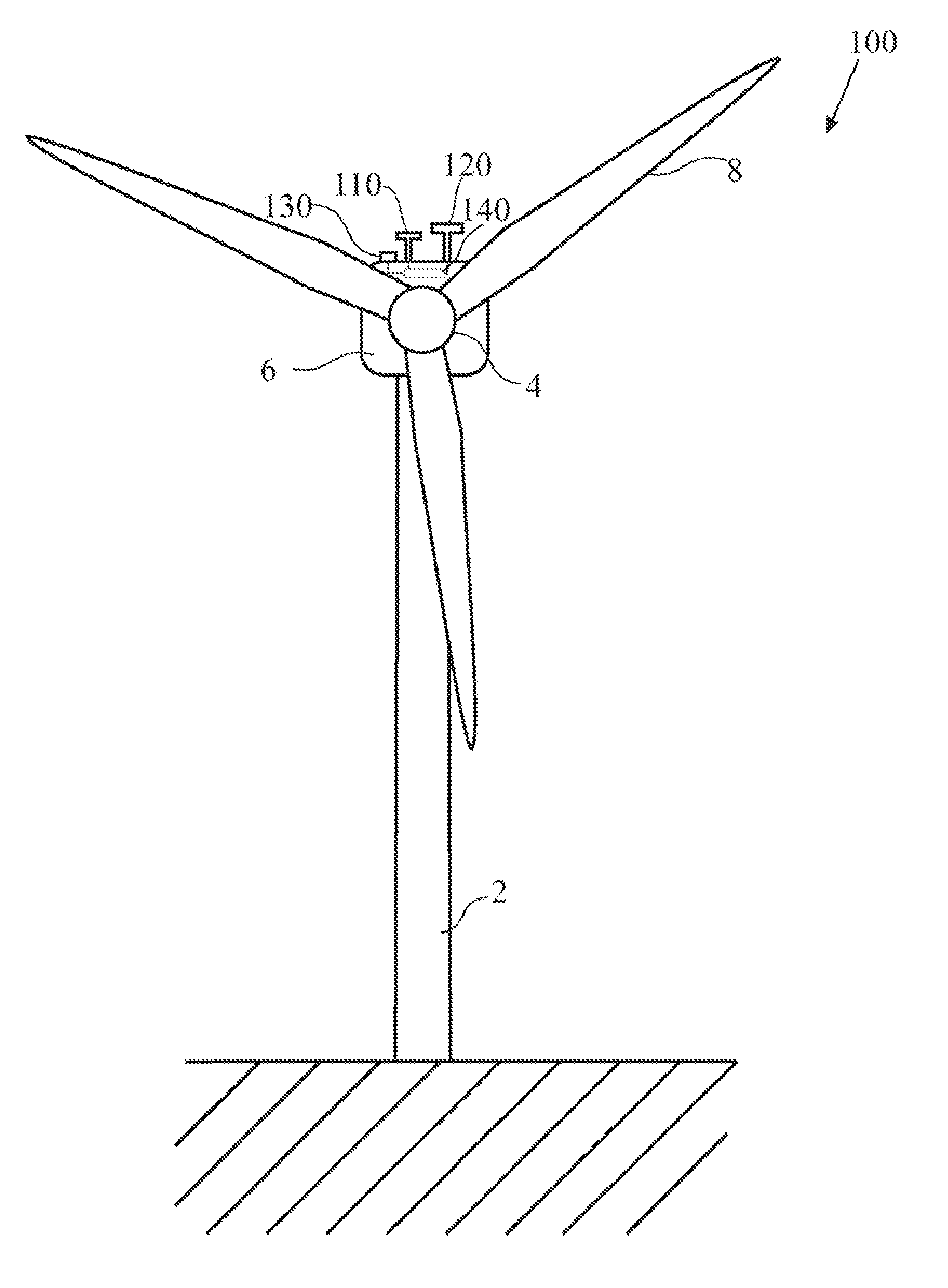
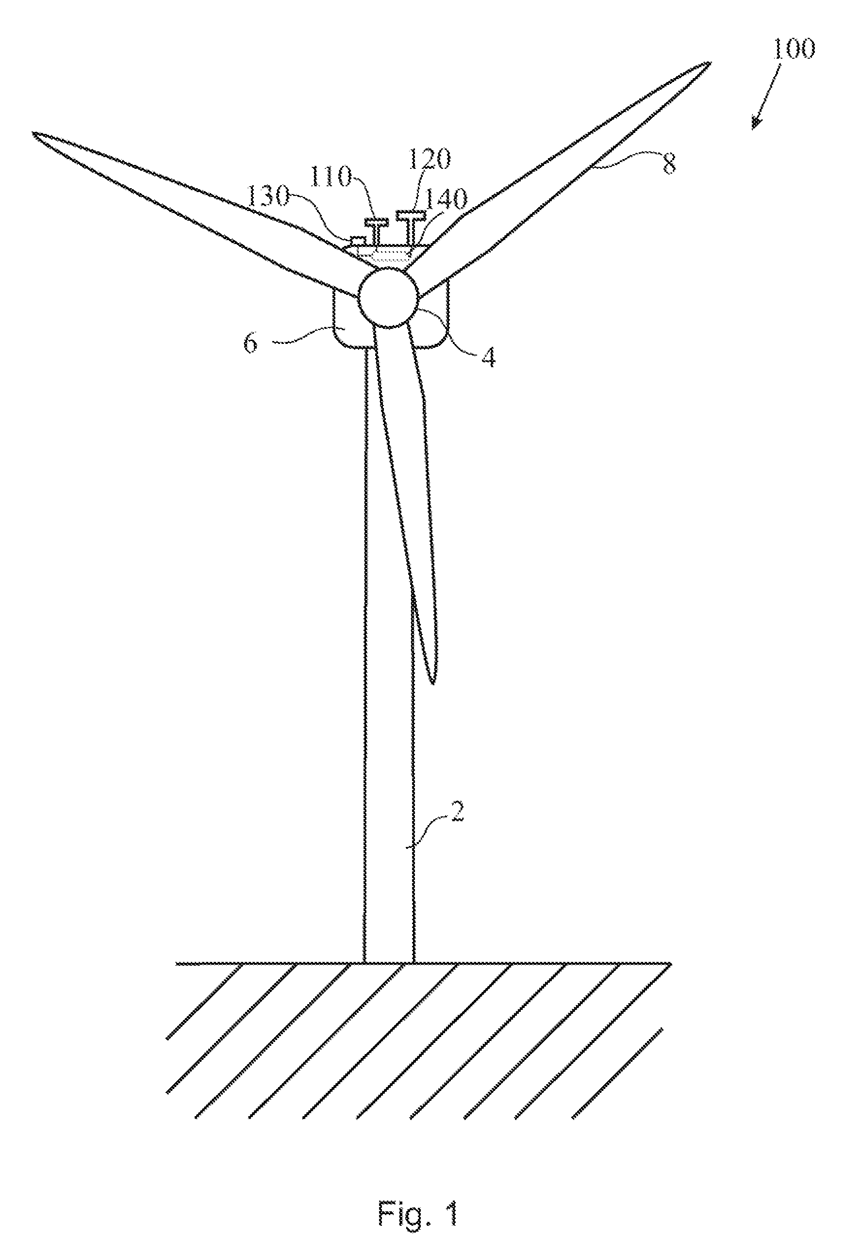
[0017]FIG. 1 illustrates an embodiment wherein the system for ice detection is provided on a win...


PUM


Abstract

A method for ice detection for a wind turbine is provided. The method includes providing an ice condition threshold parameter adapted for distinguishing a condition during which icing may occur and a condition during which icing may not occur, measuring a wind velocity with a first anemometer, wherein the first anemometer being of a first type, measuring a wind velocity with a second anemometer, wherein the second anemometer being of a second type, and wherein the second type is different from the first type, evaluating, for a condition during which icing may occur, a deviation of the wind velocity measured with the first anemometer and the wind velocity measured with the second anemometer, and determine whether the deviation exceeds a limit value based on a calibration conducted under a condition during which icing may not occur.

Description

BACKGROUND OF THE INVENTION[0001]The present invention relates to icing of wind turbines. More particularly, the invention relates to ice detection for wind turbines and an ice detection unit. Specifically, the invention relates to a method for ice detection for a wind turbine, a method for calibrating an ice detection unit, and an ice detection unit for a wind turbine.[0002]In the past, wind turbines experience an increasing demand. Therefore, more and more wind turbines are also planned and erected at sites with higher icing probability during the year. For example, such sites may be located in cold and hash climate like northern Europe, off-shore locations or alpine areas. These conditions lead to an increased probability of icing, i.e., ice accretion. Particularly, icing at the rotor blades of the turbines results in reduced energy output. This is based on increased mass loads on the wind turbine as well as in deterioration of the aerodynamic properties of the wind turbine. Furt...

Claims


Application Information

Patent Timeline
Patent Type & Authority Patents(United States)
IPC IPC(8): G01F1/00
CPCF03D11/0025F05B2260/845Y02E10/722F05B2270/80F05B2270/404F05B2260/80F05B2270/802F03D80/40Y02E10/72
Inventor ORMEL, FRANKHONEKAMP, THORSTENHOFFROGGE, CHRISTIAN
Owner GENERAL ELECTRIC CO
Learn More