Modeling delay using a discrete event execution modeling environment

a discrete event and modeling environment technology, applied in stochastic cad, instruments, cad techniques, etc., can solve the problems of high complexity of time-driven equations, unimportant clock time that each child leaves the bus, and high complexity of events, so as to achieve accurate and efficient modeled events

Active Publication Date: 2009-02-03
THE MATHWORKS INC
View PDF9 Cites 17 Cited by
  • Summary
  • Abstract
  • Description
  • Claims
  • Application Information

AI Technical Summary

Benefits of technology

[0026]The present invention provides an event-driven discrete event system (DES) modeling environment for modeling the occurrence of events independent of continuous model time. In an event-driven DES modeling environment, state transitions depend not on time, but rather asynchronous discrete incidents known as events. In one embodiment, an event-driven discrete event execution environment can be used to model a control system using one or more discrete event-driven components. As used herein, a control system may be any system that is used to maintain a desired output or control another system. The event-driven components can be used to model certain portions of a control system that cannot be accurately and efficiently modeled using a time-based model.
[0027]According to a first aspect of the invention, a method of modeling a delay in a time-based graphical representation of a control system in a graphical discrete event execution environment is provided. The method comprises a step of providing the time-based graphical representation of the control system including at least one time-driven execution component and a first event-driven execution component for modeling the delay induced in the control system. The first event-driven execution component for modeling a delay is capable of operating on at least one entity holding at least one value of arbitrary data type, and an entity definition is updatable during execution of the graphical representation of the control system. The method further comprises the step of translating a time-based signal to a set of entities in the event driven graphical discrete event execution environment that are operated on by the first event-driven execution component to model the delay. Each generated entity holds at least one value of arbitrary data type. A medium for use in a graphical discrete event modeling and execution environment on an electronic device, the medium holding instructions executable using the electronic device for performing the method for modeling a delay in a time-based graphical representation of a control system is also provided.
[0028]According to another aspect of the invention, a method of modeling a delay in a time-based graphical representation of a co

Problems solved by technology

Such systems range from simple to highly complex systems.
However, returning to the school bus example, if the user wants to know in the event of an emergency how fast the school children can get off the school bus, then the user must attempt a highly complex combination of time-driven equations and embedded event-driven models in time-driven environments to approximate the movement of each child off the bus.
Also, in such a model, the clock time that each child leaves the bus is unimportant.
Such events are highly complex to model in time-driven model executions and state-based model executions operating in time-driven environments.
Furthermore, if a user wants to model network traffic and to determine how fast a router can relay millions of packets, it is computationally costly to use the state flowchart model within the dynamic block diagram time driven environment because such a configurations require constant calls between programs.
Hence, the delay in execution output can be very noticeable, and can even approach the hardware processing limitations and bog down an execution to the point of ineffectiveness.

Method used


Image

  • Modeling delay using a discrete event execution modeling environment
  • Modeling delay using a discrete event execution modeling environment
  • Modeling delay using a discrete event execution modeling environment

Examples


Embodiment Construction

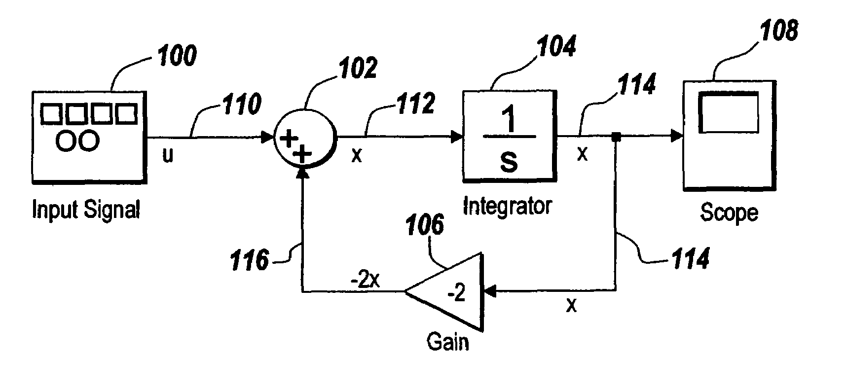
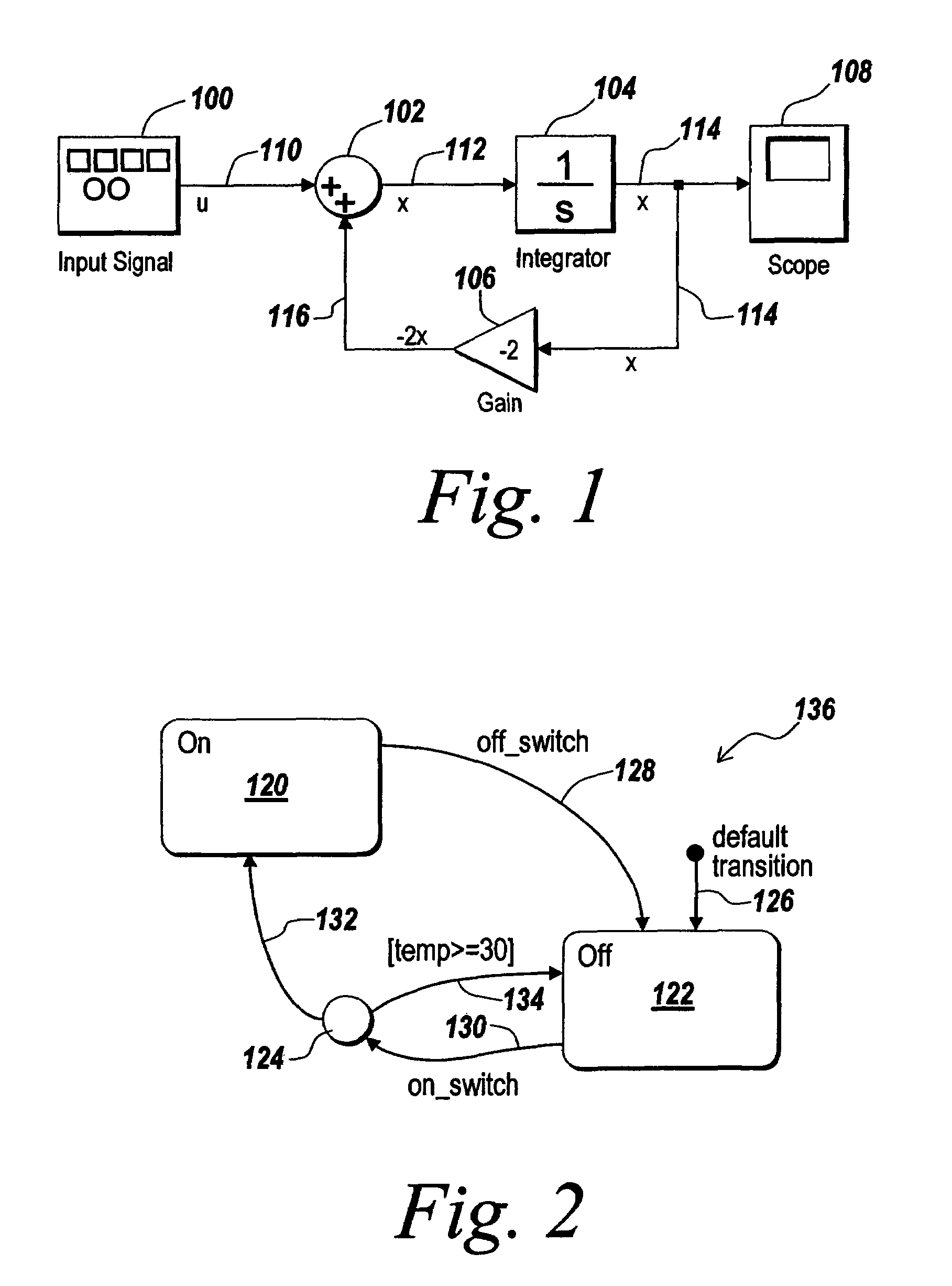
[0066]Therefore it is desired to provide a modeling environment that can model the occurrence of events independent of continuous model time. A discrete event system (DES) modeling environment is one wherein the system's state transitions depend on asynchronous discrete incidents called events. Such a model execution differs greatly from a time based model environment, such as Simulink®, wherein the execution of the model is time driven.

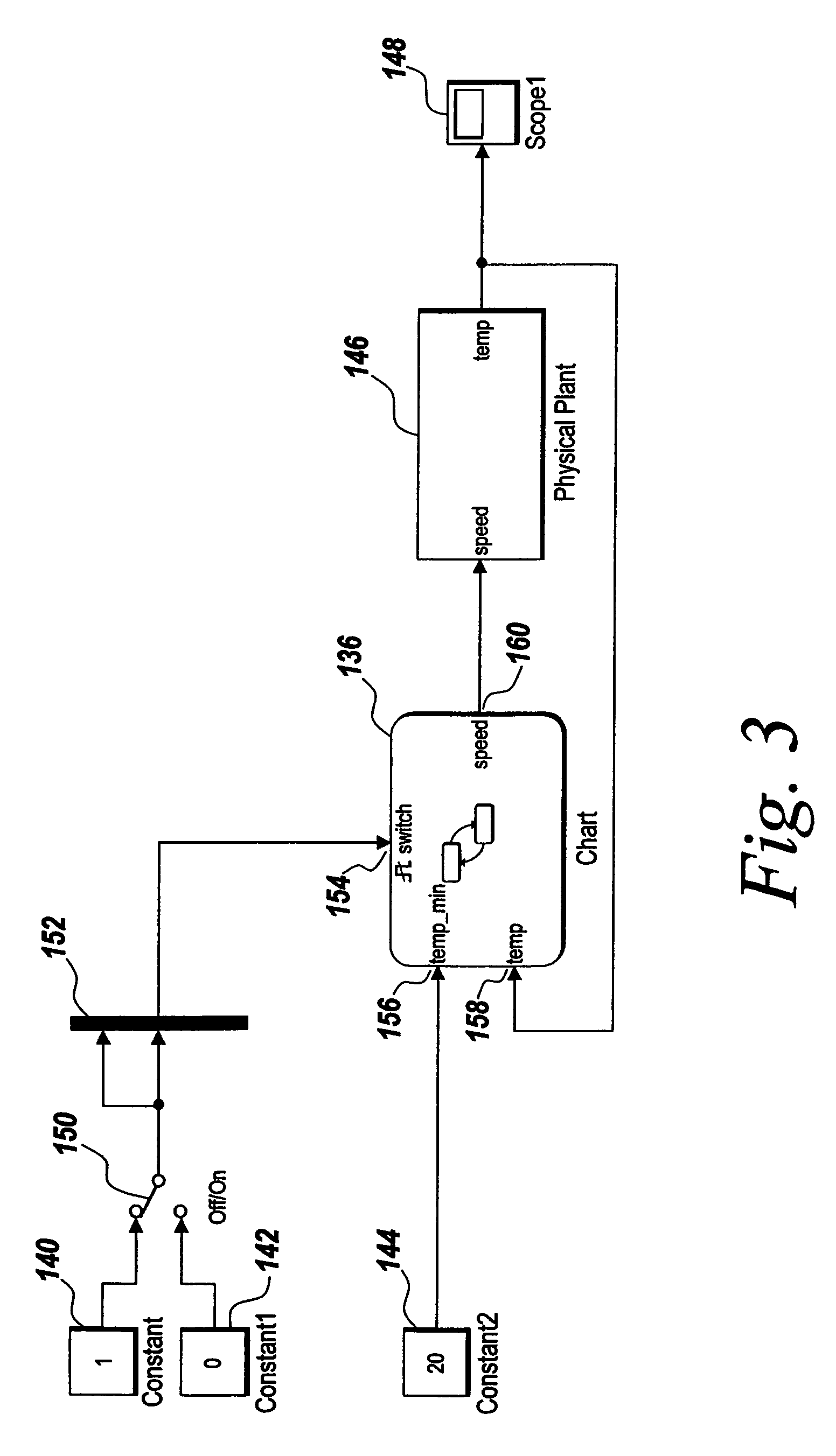
[0067]In reference to FIG. 4, a DES model environment 200 is provided. The DES model environment 200 includes an event modeling manager 201. The manager 201 coordinates the operation of the DES model environment to process model executions. The manager 201 includes a solver 203, which processes the DES model configured in the DES model environment 200. The manager 201 provides for the implementation of the DES model environment 200 by supporting the creation of DES blocks 205 that represent various aspects of the DES model. The blocks 205 can represe...


PUM


Abstract

A discrete event system (DES) modeling environment models the occurrence of events independent of continuous model time. In a DES modeling environment, state transitions depend not directly on time, but rather aperiodic discrete incidents known as events. A discrete event modeling environment can be used to model a control system using one or more discrete event-driven components. The event-driven components can be used to model certain portions of a control system that cannot be accurately modeled using a time-based model.

Description

RELATED APPLICATIONS[0001]The present application claims priority to U.S. Provisional Patent Application Ser. No. 60 / 611,572, entitled “Modeling Feedback Loops Using a Discrete Event Simulation Modeling Environment”, filed Sep. 20, 2004 and U.S. Provisional Patent Application Ser. No. 60 / 611,571, filed on Sep. 20, 2004, entitled “Method and System for Transferring Data Between a Discrete Event Simulation Environment and an External Environment”, the contents of both of which are herein incorporated by reference.FIELD OF THE INVENTION[0002]The present invention relates to modeling of discrete or time events using a graphical modeling system. More particularly, the present invention relates to configuring parameters of a block in a graphical model used to model discrete time events.BACKGROUND OF THE INVENTION[0003]Generally, graphical analysis, simulation, and execution methods are used in modeling, design, analysis, and synthesis of engineered systems. These methods provide a visual ...

Claims


Application Information

Patent Timeline
IPC IPC(8): G06G7/62G06F40/00
CPCG06F17/5009G06F2217/10G06F2217/84G06F30/20G06F2111/08G06F2119/12
Inventor CLUNE, MICHAEL I.GRACE, ANDREWYEDDANAPUDI, MURALIMANI, RAMAMURTHYMOSTERMAN, PIETER J.SURI, ATUL
Owner THE MATHWORKS INC
Why Eureka
Try Eureka