
Method and system for providing a spin transfer device with improved switching characteristics

a technology of spin transfer device and switching characteristic, applied in the field of magnetic random access memory, can solve the problem of significant limitations imposed on the maximum allowed switching curren

Inactive Publication Date: 2009-02-03
SAMSUNG SEMICON
View PDF10 Cites 185 Cited by
  • Summary
  • Abstract
  • Description
  • Claims
  • Application Information

AI Technical Summary

Benefits of technology

This configuration improves switching characteristics by allowing smaller write currents, reducing thermal stability, and minimizing the impact of selection transistor limitations, while maintaining data retention and signal quality.

Problems solved by technology

For example, significant limitations may be imposed on the maximum allowed switching current to be passed through the conventional magnetic element 10.

Method used


Image

  • Method and system for providing a spin transfer device with improved switching characteristics
  • Method and system for providing a spin transfer device with improved switching characteristics
  • Method and system for providing a spin transfer device with improved switching characteristics

Examples


Embodiment Construction

[0027]The method and system relate to magnetic memories. The following description is presented to enable one of ordinary skill in the art to make and use the method and system and is provided in the context of a patent application and its requirements. Various modifications to the embodiments and the generic principles and features described herein will be readily apparent to those skilled in the art. Thus, the method and system are not intended to be limited to the embodiments shown, but is to be accorded the widest scope consistent with the principles and features described herein.

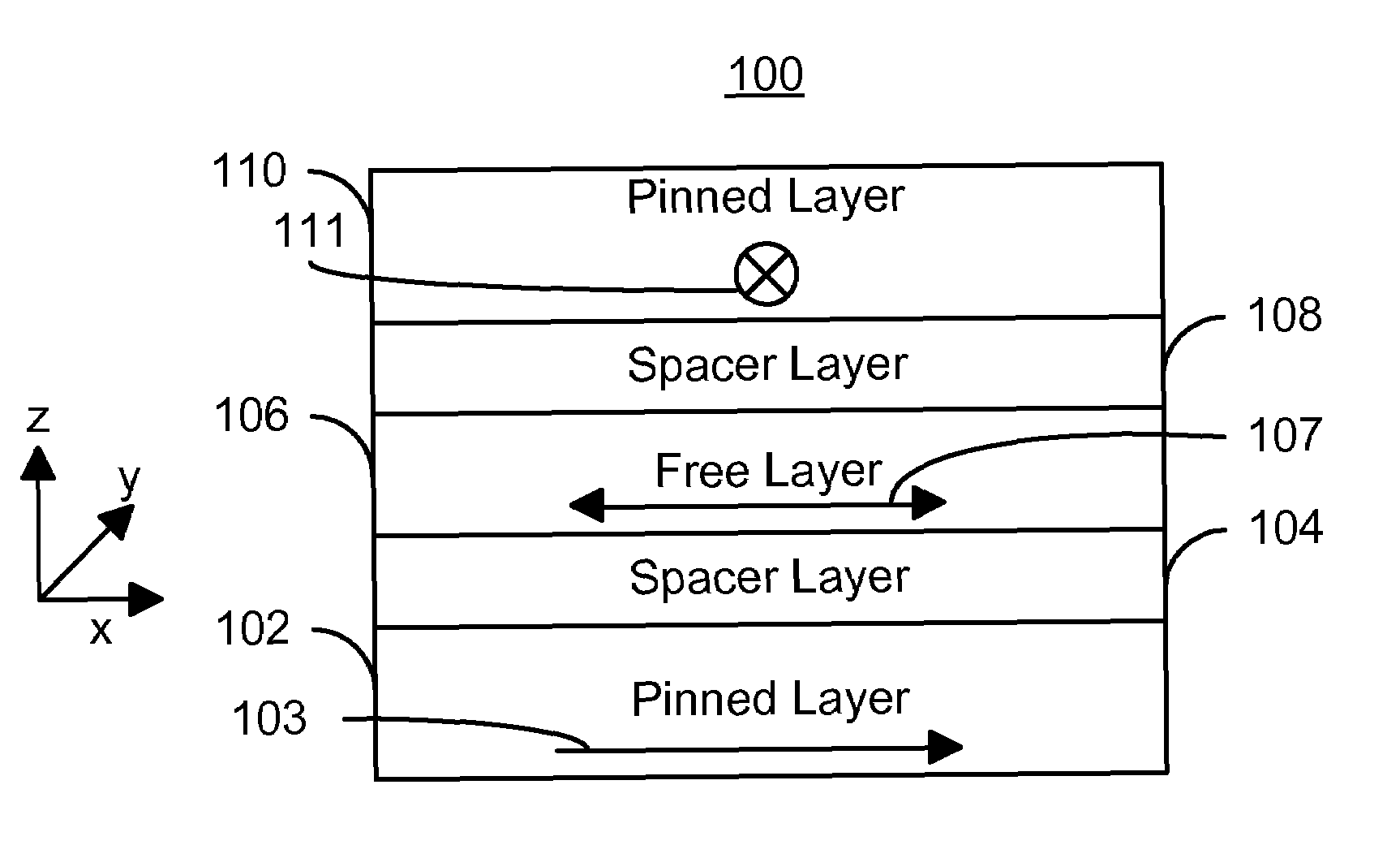
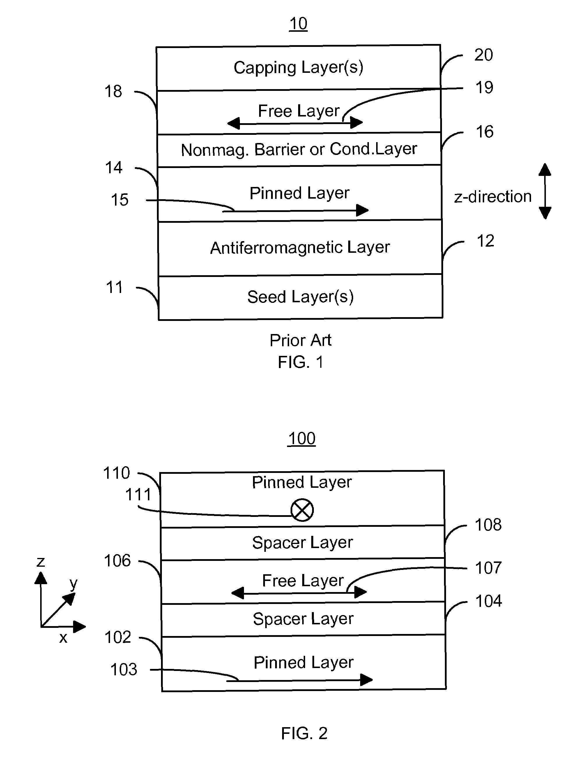
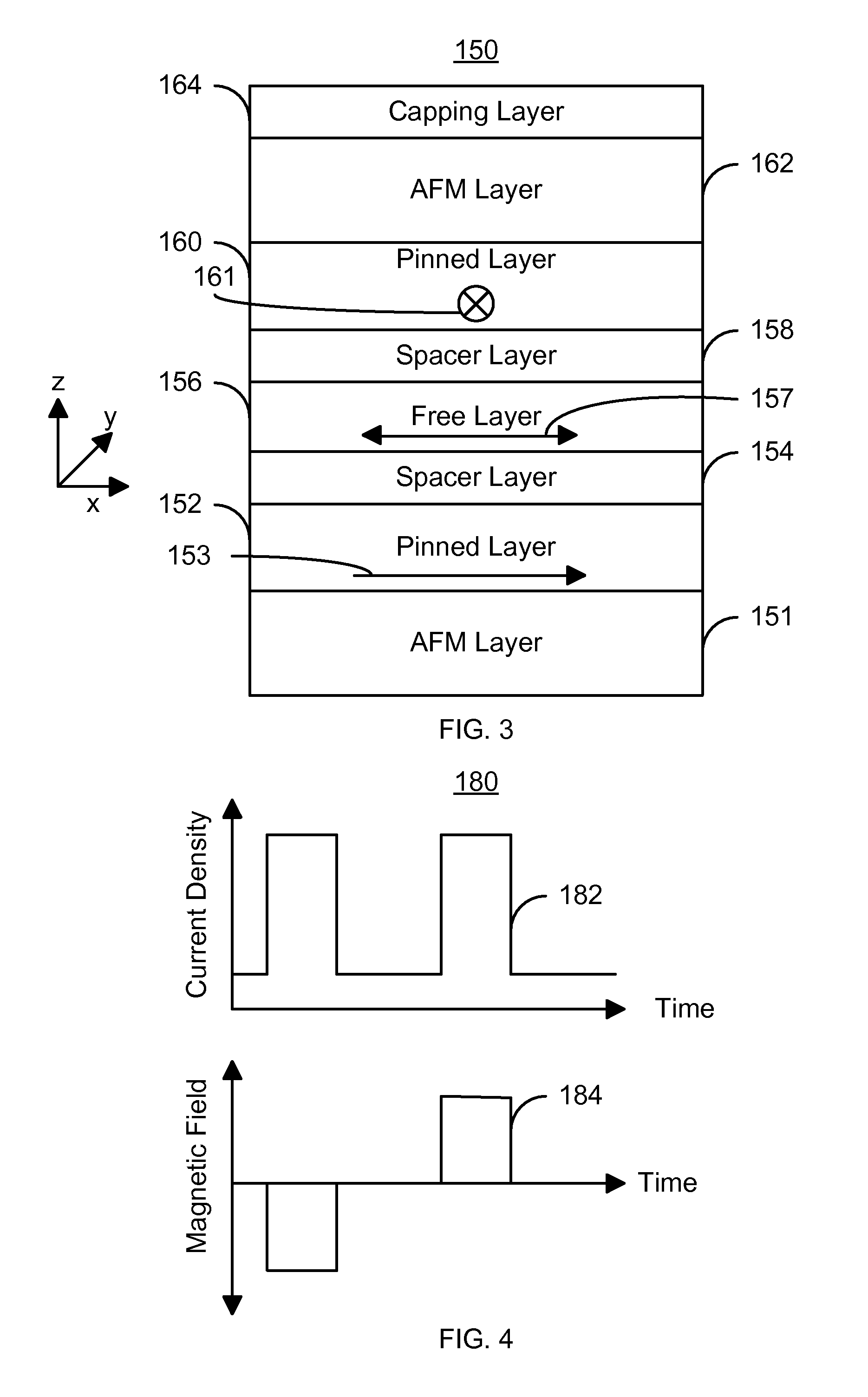
[0028]A method and system for providing a magnetic element is described. The magnetic element includes a first pinned layer, a first spacer layer, a free layer, a second spacer layer, and a second pinned layer. The first and second pinned layers have first and second magnetizations oriented in first and second directions, respectively. The first and second spacer layers are nonferromagnetic. The first a...


PUM


Abstract

A method and system for providing a magnetic element is described. The magnetic element includes a first pinned layer, a first spacer layer, a free layer, a second spacer layer, and a second pinned layer. The first and second pinned layers have first and magnetizations oriented in first and second directions, respectively. The first and second spacer layers are nonferromagnetic. The first and second spacer layers are between the free layer and the first and second pinned layers, respectively. The magnetic element is configured either to allow the free layer to be switched to each of multiple states when both a unidirectional write current is passed through the magnetic element and the magnetic element is subjected to a magnetic field corresponding to the each states or to allow the free layer to be switched to each of the plurality of states utilizing a write current and an additional magnetic field that is applied from at least one of the first pinned layer and the second pinned layer substantially only if the write current is also applied.

Description

CROSS-REFERENCE TO RELATED APPLICATIONS[0001]The present application claims priority from co-pending provisional patent application Ser. No. 60 / 939,329 filed May 21, 2007 entitled “Method and System for Providing a Spin Transfer Device with Improved Switching Characteristics” and assigned to the assignee of the present application.BACKGROUND OF THE INVENTION[0002]Magnetic memories, particularly magnetic random access memories (MRAMs), have drawn increasing interest due to their potential for high read / write speed, excellent endurance, non-volatility and low power consumption during operation. An MRAM can store information utilizing magnetic materials as an information recording medium. Typically, a conventional magnetic element is used for storing data in such magnetic memories.[0003]FIG. 1 depicts a conventional magnetic element 10, which may be a conventional magnetic tunneling junction (MTJ) or a conventional spin valve. The conventional magnetic element 10 may be used in a conve...

Claims


Application Information

Patent Timeline
Patent Type & Authority Patents(United States)
IPC IPC(8): G11C11/15
CPCG11C11/16G11C11/161G11C11/1675
Inventor APALKOV, DMYTROLI, ZHANJIE
Owner SAMSUNG SEMICON
Learn More