
Method and apparatus for taking an image, method and apparatus for processing an image, and program and storage medium

a technology for taking images and programs, applied in the field of apparatus and methods for taking images, which can solve the problems of many cameras and achieve the effect of easy image taking

Inactive Publication Date: 2009-02-03
SONY CORP
View PDF7 Cites 5 Cited by
  • Summary
  • Abstract
  • Description
  • Claims
  • Application Information

AI Technical Summary

Benefits of technology

[0008]In view of the above, it is an object of the present invention to provide a technique of easily taking an image of a subject seen from a plurality of viewpoints by using a single camera.

Problems solved by technology

However, in the method in which many cameras are placed around a subject, the problem is that many cameras are needed.

Method used


Image

  • Method and apparatus for taking an image, method and apparatus for processing an image, and program and storage medium
  • Method and apparatus for taking an image, method and apparatus for processing an image, and program and storage medium
  • Method and apparatus for taking an image, method and apparatus for processing an image, and program and storage medium

Examples


first embodiment

[0098]FIG. 4 shows an example of a construction of the optical system 101 for capturing light rays at continuously varying viewpoints shown in FIG. 2 and an example of a construction the omnidirectional image capture unit 102 shown in FIG. 2, according to the present invention.

[0099]In the embodiment shown in FIG. 4, the optical system 101 for capturing light rays at continuously varying viewpoints is constructed in the form of an elliptic mirror 111.

[0100]The elliptic mirror 111 has a shape obtained rotating an ellipse about a major axis (or minor axis) and dividing the resultant body of revolution into two pieces by cutting it along a plane containing the major axis (or the minor axis). The elliptic mirror 111 has a hollow space on the inner side thereof, and a reflecting surface for reflecting light is formed on the inner surface of the elliptic mirror 111. The elliptic mirror 111 is disposed such that a subject is located at one focal point f2 of two focal points f1 and f2 of th...

second embodiment

[0104]FIG. 5 shows an example of a construction of the optical system 101 for capturing light rays at continuously varying viewpoints shown in FIG. 2 and an example of a construction the omnidirectional image capture unit 102 shown in FIG. 2, according to the present invention. In FIG. 4, similar parts to those in FIG. 4 are denoted by similar reference numerals and they are not described unless a further description is necessary.

[0105]In the embodiment shown in FIG. 5, an optical system 101 for capturing light rays at continuously varying viewpoints is formed of two parabolic mirrors 121A and 121B.

[0106]The parabolic mirrors 121A and 121B each have a shape obtained by rotating a parabola expressed, for example, by y=x2 about the y axis, and a reflecting surface for reflecting light is formed on the inner surface thereof. The parabolic mirrors 121A and 121B are disposed such that optical axes thereof are coincident with each other and such that their openings (at ends opposite to ve...


PUM


Abstract

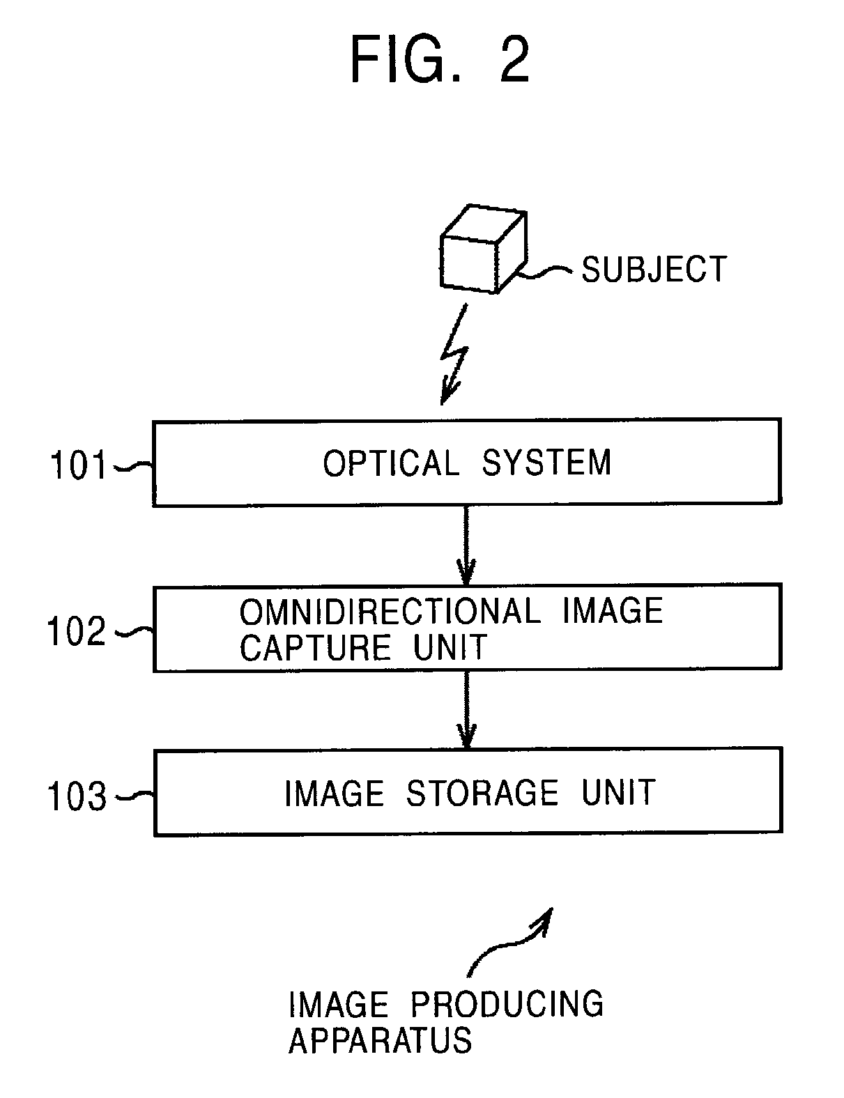
An image producing apparatus is capable of producing image data representing an image of a subject seen from a wide range of directions. An elliptic mirror reflects light radiated from a subject located at one of two focal points of the elliptic mirror. The light reflected by the elliptic mirror travels toward the other one of the two focal points of the elliptic mirror and falls on a fisheye camera disposed at the other one of the two focal points. The fisheye camera senses the incident light and takes an image of the subject.

Description

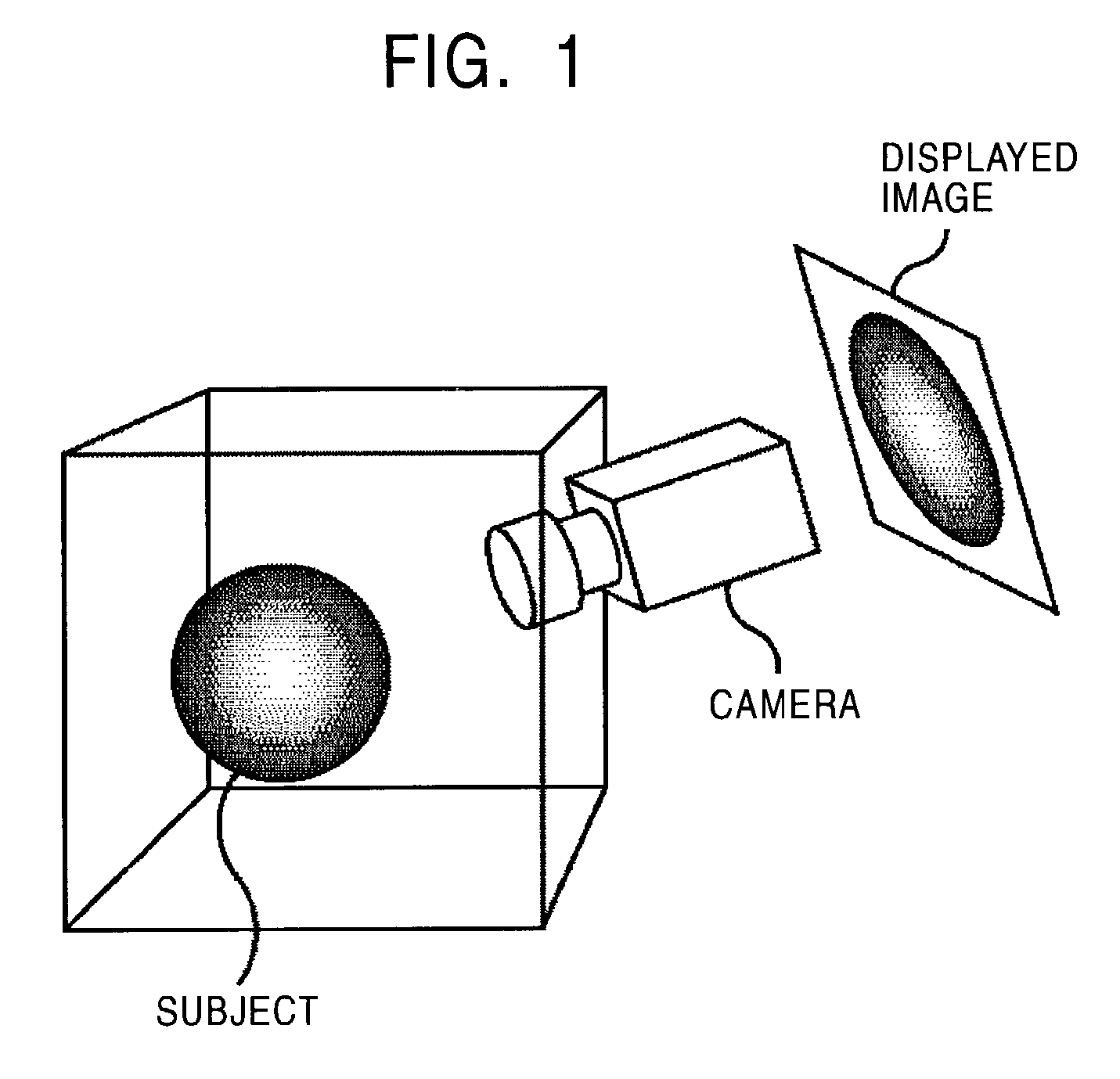
BACKGROUND OF THE INVENTION[0001]1. Field of the Invention[0002]The present invention relates to an apparatus and method for taking an image, an apparatus and method for processing an image, a program, and a storage medium and more particularly, to an apparatus and method for taking an image, an apparatus and method for processing an image, a program, and a storage medium, for allowing an image of a subject seen from all directions to be easily taken and displayed.[0003]2. Description of the Related Art[0004]In conventional displays using, for example, cathode ray tube (CRT), liquid crystal panel, or a projector, an image of a subject taken by a video camera (hereinafter, also referred to simply as a camera) or the like is displayed in a simple manner such that the image displayed represents, as shown in FIG. 1, the subject seen from a viewpoint at which the camera is located.[0005]That is, the camera can take only an image of a subject seen from the location of the camera, and the ...

Claims


Application Information

Patent Timeline
Patent Type & Authority Patents(United States)
IPC IPC(8): H04N5/225G06T1/00G03B35/00H04N5/74
CPCG03B35/00
Inventor KONDO, TETSUJIROTANAKA, KENJI
Owner SONY CORP
Learn More