Landing gear noise reduction
a technology of landing gear and noise reduction, applied in the field of landing gear, can solve the problems of eddy current(s), turbulent air flow that generates extra noise, and flow being created, and achieve the effect of less nois
- Summary
- Abstract
- Description
- Claims
- Application Information
AI Technical Summary
Benefits of technology
Problems solved by technology
Method used
Image

Examples
first embodiment
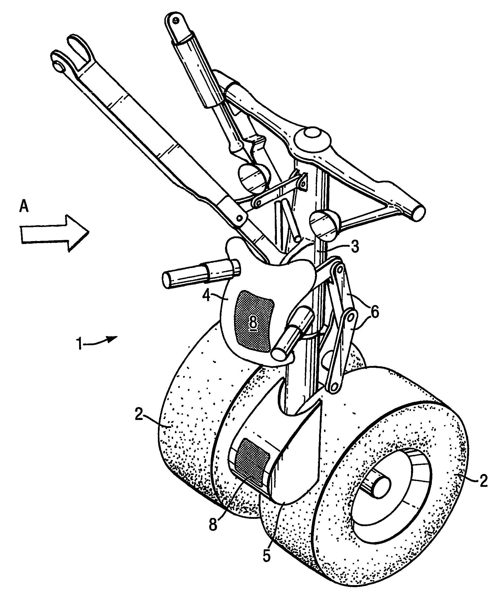
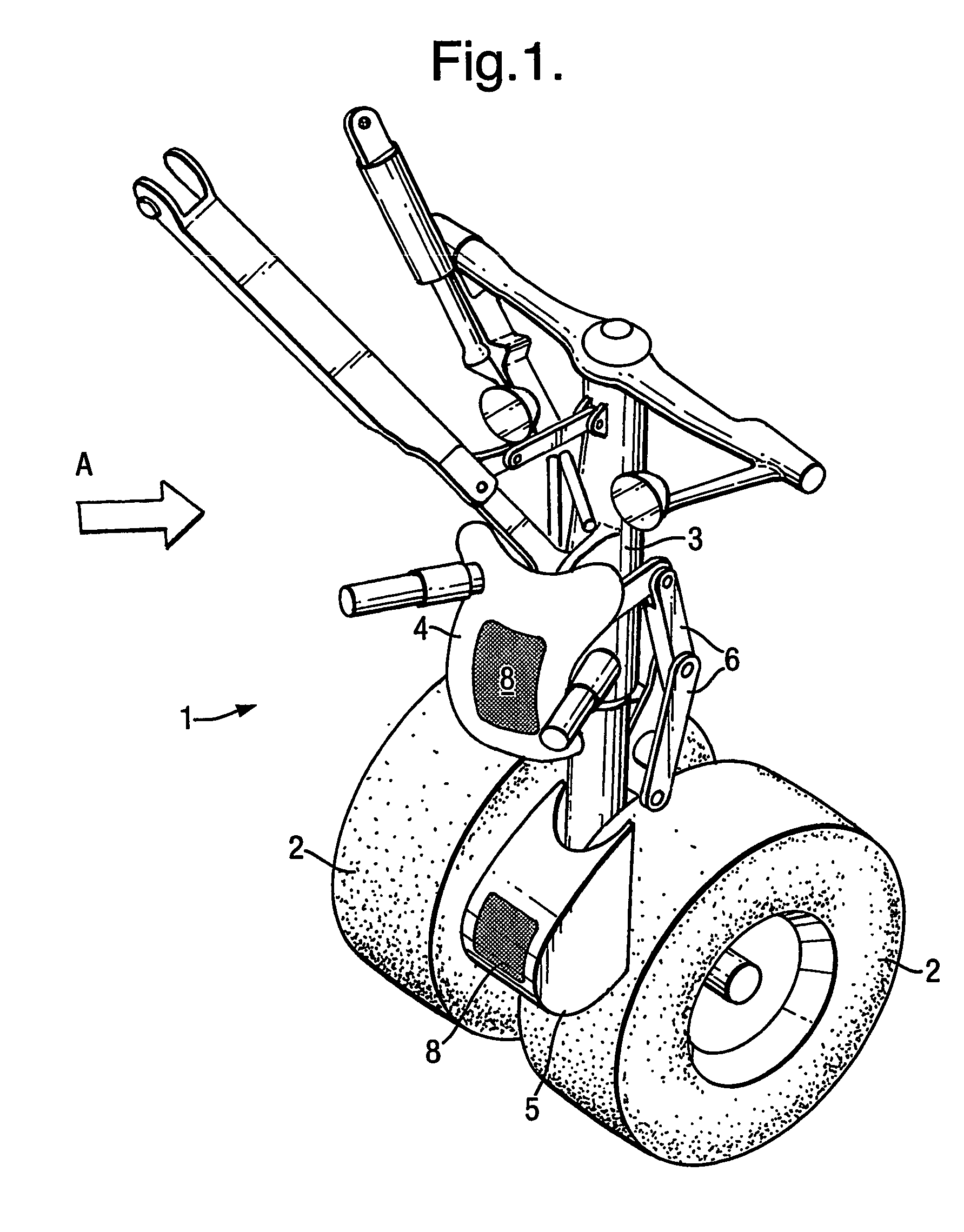
[0042]FIG. 1 illustrates the invention concerning a nose landing gear 1. The nose landing gear 1 includes wheels 2 a central support column 3 (or leg) and an upper fairing 4 and a lower fairing 5. The nose gear 1 is shown in its deployed position during landing of an aircraft (not shown in FIG. 1) to which the nose landing gear 1 is attached. The direction of flow of air relative to the nose gear is indicated by arrow A which points to the right in FIG. 1, since the nose gear and aircraft are moving to the left.
[0043]The upper fairing 4 is positioned over the central support column 3 in a position that shields parts 6 of the landing structure that are associated with the steering of the nose gear wheels 2. The parts 6 that are shielded by the fairing include steering actuators (comprising rods, linkages and the like) that would if not shielded generate significant noise. The upper fairing 4 is attached to the gear 1 via steering actuator mounting brackets. The upper fairing 4 has re...
second embodiment
[0054]the invention is shown in FIG. 3, which shows a main landing gear 11 including wheels 2 and a central support column 3 (or leg). The gear 11 includes several fairings 12, 13, 14, 15. The main gear 11 is shown in its deployed position during landing of an aircraft (not shown in FIG. 3) to which the main landing gear 11 is attached. The direction of flow of air relative to the landing gear is indicated by arrow B which points to the left in FIG. 3, since the main landing gear and aircraft are moving to the right.
[0055]The fairings illustrated in FIG. 3 include an undertray fairing 12, an articulation-link fairing 13, a door / dragstay-closure fairing 14 and an upper side-stay fairing 15. Each fairing includes, in a manner similar to that of the fairings shown in FIG. 1, a perforated region 8 which covers a stagnation point or part of a stagnation line. Thus the principles behind and improvements provided by the arrangement of the fairings shown in FIG. 3 and the perforated regions...
PUM
 Abstract
Description
Claims
Application Information
 - R&D
- Intellectual Property
- Life Sciences
- Materials
- Tech Scout
- Unparalleled Data Quality
- Higher Quality Content
- 60% Fewer Hallucinations
Browse by: Latest US Patents, China's latest patents, Technical Efficacy Thesaurus, Application Domain, Technology Topic, Popular Technical Reports.
© 2025 PatSnap. All rights reserved.Legal|Privacy policy|Modern Slavery Act Transparency Statement|Sitemap|About US| Contact US: help@patsnap.com