
Jack element in communication with an electric motor and or generator

a technology of electric motors and jack elements, applied in the field of drill bits, can solve the problems of damage to drill bits, harsh conditions on drill bits, and expensive and time-consuming replacement of drill bits in the field,

Inactive Publication Date: 2009-02-03
SCHLUMBERGER TECH CORP
View PDF124 Cites 50 Cited by
  • Summary
  • Abstract
  • Description
  • Claims
  • Application Information

AI Technical Summary

Benefits of technology

The patent describes a drill bit with a jack assembly that includes a spring and an electric motor. The electric motor can change the compression of the spring and can be connected to downhole telemetry or electronic equipment. The drill bit can be a shear bit, percussion bit, or roller cone bit. The jack assembly can be used to steer the drill bit or to control its orientation. The distal end of the drill bit can have a bias to guide it in the direction of the drill bit's rotation. The patent also describes the use of different materials for the distal end of the drill bit, such as diamond or cemented metal carbide. The technical effects of this patent include improved control and steering of drill bits, improved fluid flow, and improved performance in drilling and wellbore construction.

Problems solved by technology

Often drill bits are subjected to harsh conditions when drilling below the earth's surface.
Replacing damaged drill bits in the field is often costly and time consuming since the entire downhole tool string must typically be removed from the borehole before the drill bit can be reached.
Bit whirl in hard formations may result in damage to the drill bit and reduce penetration rates.
Further, loading too much weight on the drill bit when drilling through a hard formation may exceed the bit's capabilities and also result in damage.
Too often unexpected hard formations are encountered suddenly and damage to the drill bit occurs before the weight on the drill bit may be adjusted.

Method used


Image

  • Jack element in communication with an electric motor and or generator
  • Jack element in communication with an electric motor and or generator
  • Jack element in communication with an electric motor and or generator

Examples


Embodiment Construction

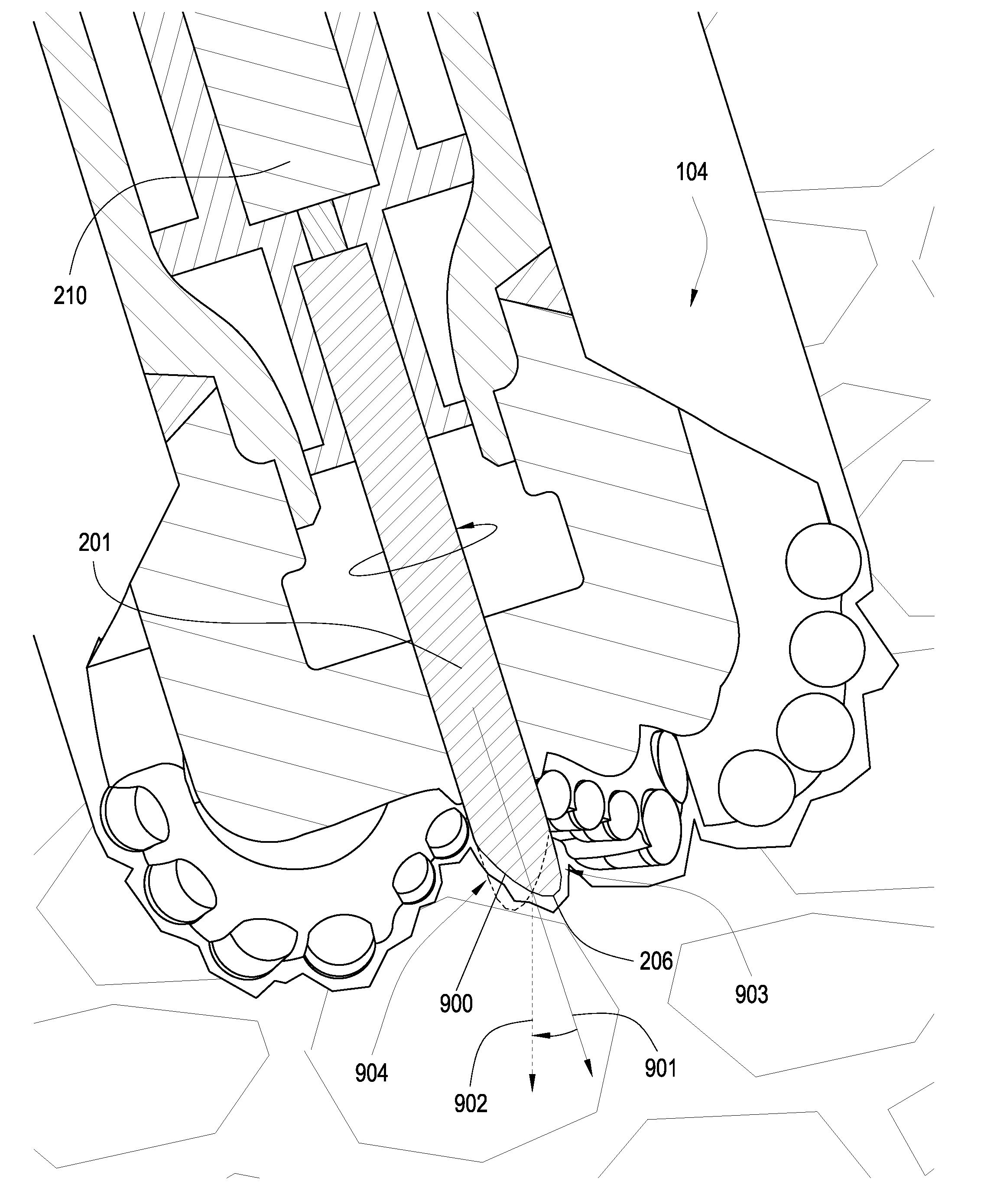
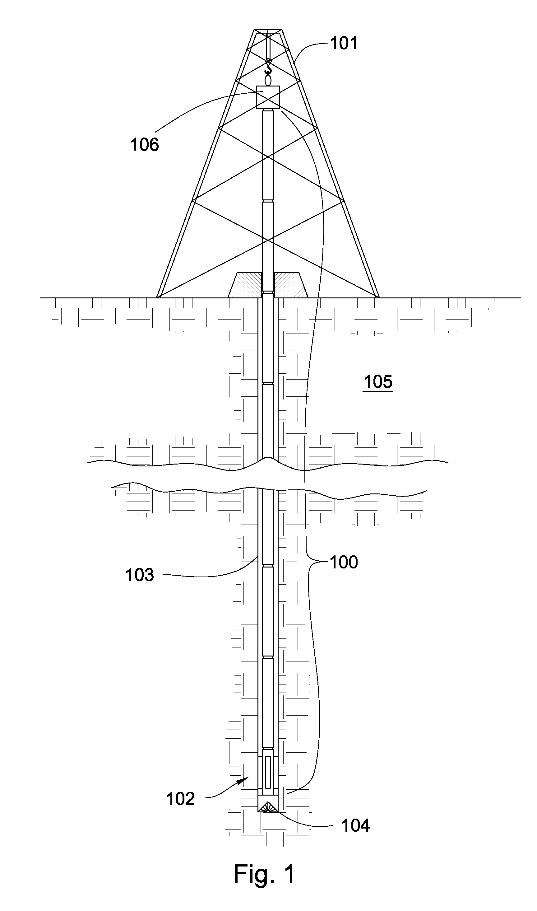
[0024]FIG. 1 is an embodiment of a tool string 100 suspended by a derrick 101. A bottom-hole assembly 102 is located at the bottom of a bore hole 103 and comprises a drill bit 104. As the drill bit 104 rotates downhole the tool string 100 advances farther into the earth. The tool string may penetrate soft or hard subterranean formations 105. The bottom-hole assembly 102 and / or downhole components may comprise data acquisition devices which may gather data. The data may be sent to the surface via a transmission system to a data swivel 106. The data swivel 106 may send the data to the surface equipment. Further, the surface equipment may send data and / or power to downhole tools and / or the bottom-hole assembly 102. A preferred data transmission system is disclosed in U.S. Pat. No. 6,670,880 to Hall, which is herein incorporated by reference for all that it discloses. However, in some embodiments, the no telemetry system is used. Mud pulse, short hop, or EM telemetry systems may also be...


PUM


Abstract

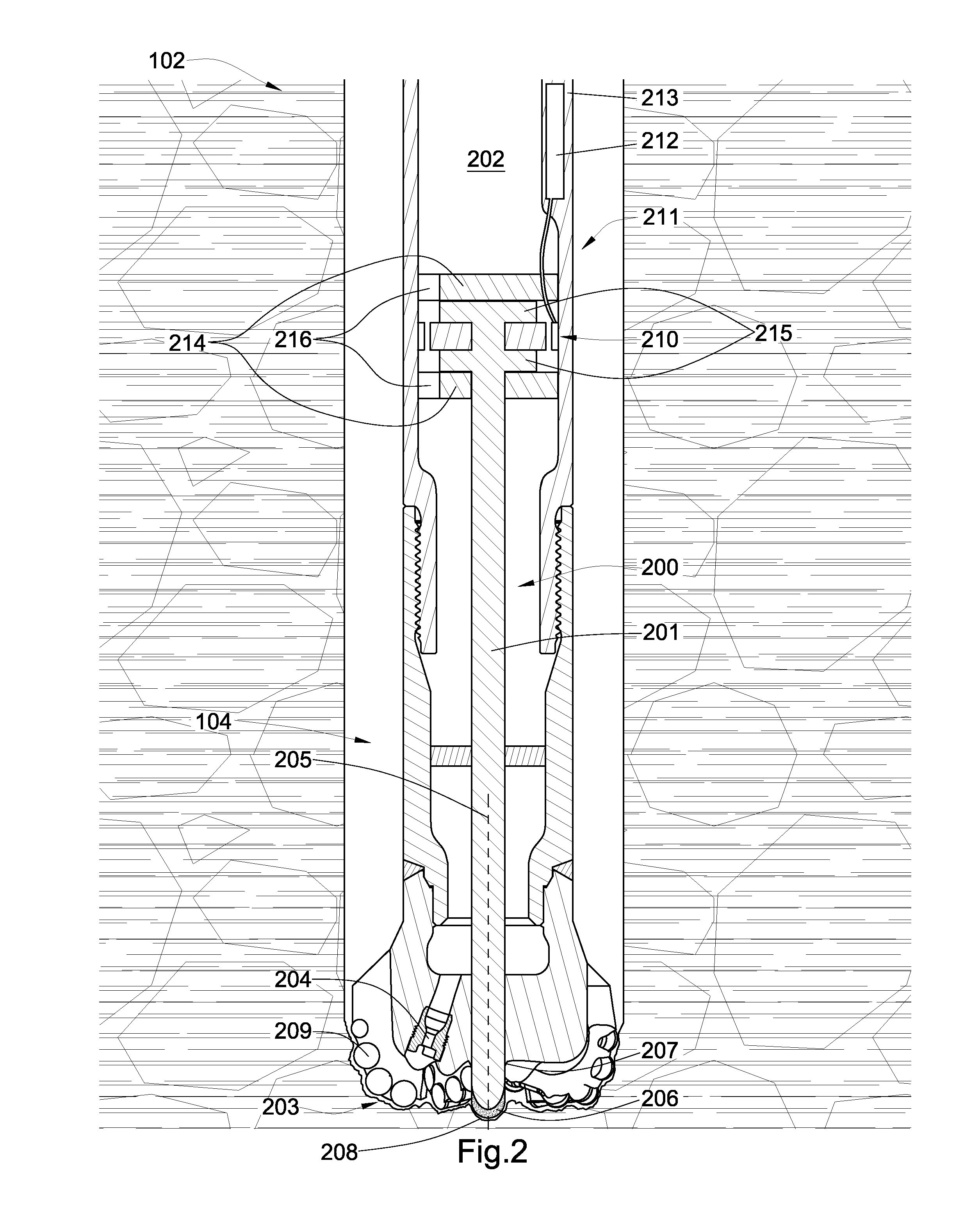
A drill bit has a body intermediate a shank and a working face and has an axis of rotation. The working face has at least one cutting element and the body has at least a portion of a jack assembly. The jack assembly has at least a portion of a shaft disposed within a cavity formed in the body of the drill bit, the shaft having a distal end extending from an opening of the cavity formed in the working face. The jack assembly also has an electric motor and / or generator.

Description

CROSS REFERENCE TO RELATED APPLICATIONS[0001]This patent application is a continuation-in-part of U.S. patent application Ser. No. 11 / 611,310 filed on Dec. 15, 2006 and which is entitled System for Steering a Drill String. This patent application is also a continuation-in-part of U.S. patent application Ser. No. 11 / 278,935 filed on Apr. 6, 2006 now U.S. Pat. No. 7,426,968 and which is entitled Drill Bit Assembly with a Probe. U.S. patent application Ser. No. 11 / 278,935 is a continuation-in-part of U.S. patent application Ser. No. 11 / 277,394, now U.S. Pat. No. 7,398,837, which filed on Mar. 24, 2006 and entitled Drill Bit Assembly with a Logging Device. U.S. patent application Ser. No. 11 / 277,394 is a continuation-in-part of U.S. patent application Ser. No. 11 / 277,380, now U.S. Pat. No. 7,337,858, also filed on Mar. 24, 2006 and entitled A Drill Bit Assembly Adapted to Provide Power Downhole. U.S. patent application Ser. No. 11 / 277,380 is a continuation-in-part of U.S. patent applica...

Claims


Application Information

Patent Timeline
Patent Type & Authority Patents(United States)
IPC IPC(8): E21B7/04E21B10/00
CPCE21B4/06E21B6/00E21B7/24E21B10/46E21B10/54E21B10/62
Inventor HALLWILDE, TYSON J.MISKIN, BEN
Owner SCHLUMBERGER TECH CORP
Learn More