
System, method and apparatus for controlling converters using input-output linearization

a technology of input-output linearization and system, applied in the direction of electric variable regulation, process and machine control, instruments, etc., can solve the problems of unstable operating point, nonlinear operation of control loop, and difficult control of system under these nonlinear effects, and achieve the effect of convenient implementation

Inactive Publication Date: 2009-01-27
BOARD OF RGT THE UNIV OF TEXAS SYST
View PDF9 Cites 13 Cited by
  • Summary
  • Abstract
  • Description
  • Claims
  • Application Information

AI Technical Summary

Benefits of technology

This approach provides a stable linear system with left-half plane zeros, enabling control of power converters without instability, even during startup and transient conditions, and allows for programmable parameters for easy implementation on DSPs or ASICs.

Problems solved by technology

Switching from one state to another and the accompanying nonlinearity of the system causes problems.
But, control of the system under these nonlinear effects becomes difficult when certain performance objectives must be met.
However, use of this method requires making several assumptions, one of them being so-called “small signal operation.” This works well for asymptotic stability in the neighborhood of the operating point, but ignores large signal effects which can result in nonlinear operation of the control loop when, for example, an amplifier saturates during startup, or during transient modes, such as load or input voltage changes.
Unstable zero dynamics associated with TEM in the continuous conduction mode (CCM) prevent the use of an input-output feedback linearization because it would result in an unstable operating point.

Method used


Image

  • System, method and apparatus for controlling converters using input-output linearization
  • System, method and apparatus for controlling converters using input-output linearization
  • System, method and apparatus for controlling converters using input-output linearization

Examples


Embodiment Construction

[0039]While the making and using of various embodiments of the present invention are discussed in detail below, it should be appreciated that the present invention provides many applicable inventive concepts that can be embodied in a wide variety of specific contexts. The specific embodiments discussed herein are merely illustrative of specific ways to make and use the invention and do not delimit the scope of the invention.

[0040]The present invention provides a system, method and apparatus for controlling converters using input-output linearization that does not constrain stability to one operating point, but rather to a set of operating points spanning the expected range of operation during startup and transient modes of operation. In particular, the present invention uses leading-edge modulation and input-output linearization to compute the duty ratio of a boost converter or a buck-boost converter. The present invention can also be applied to other converter types. Moreover, the ...


PUM


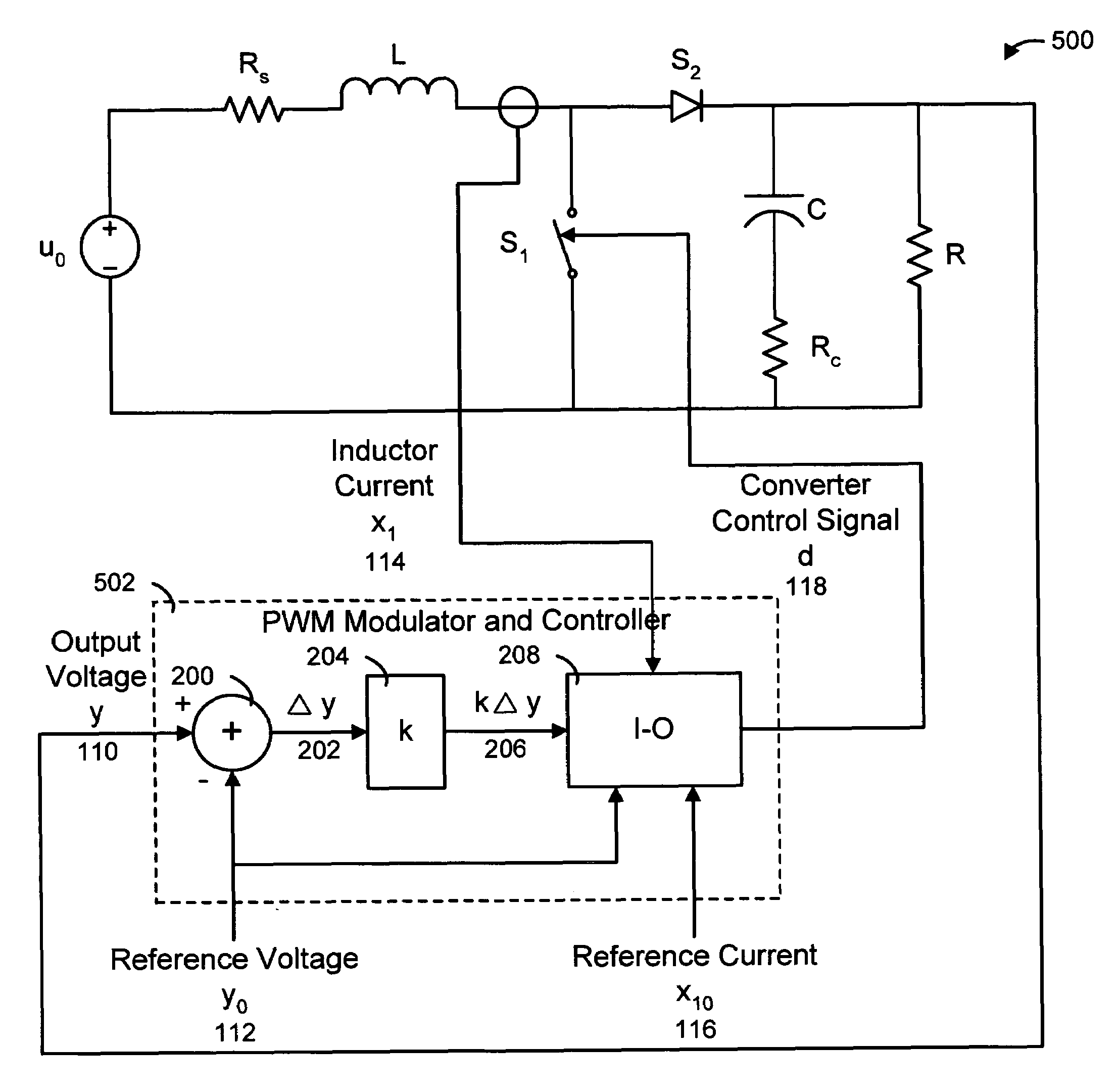
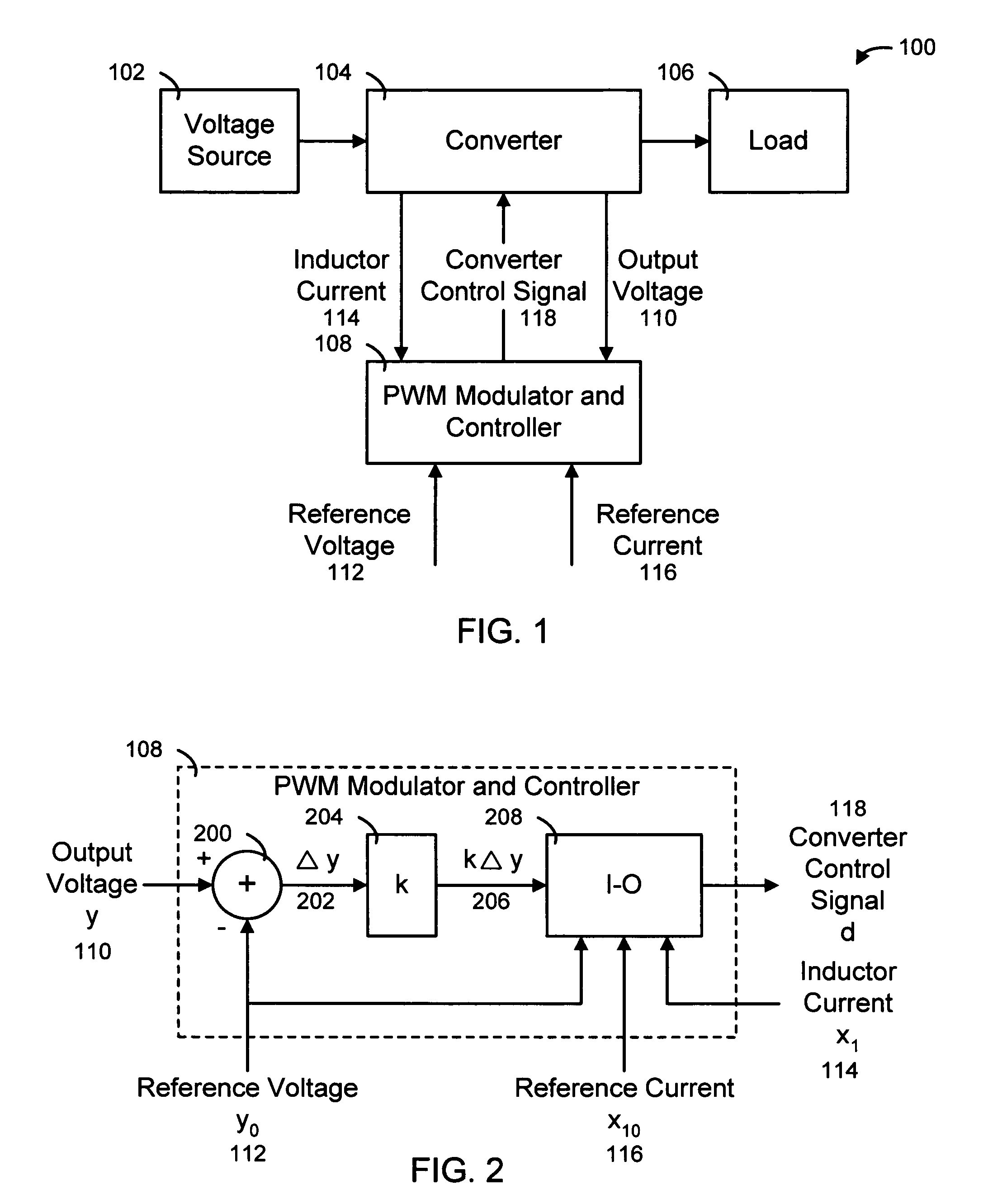
Abstract

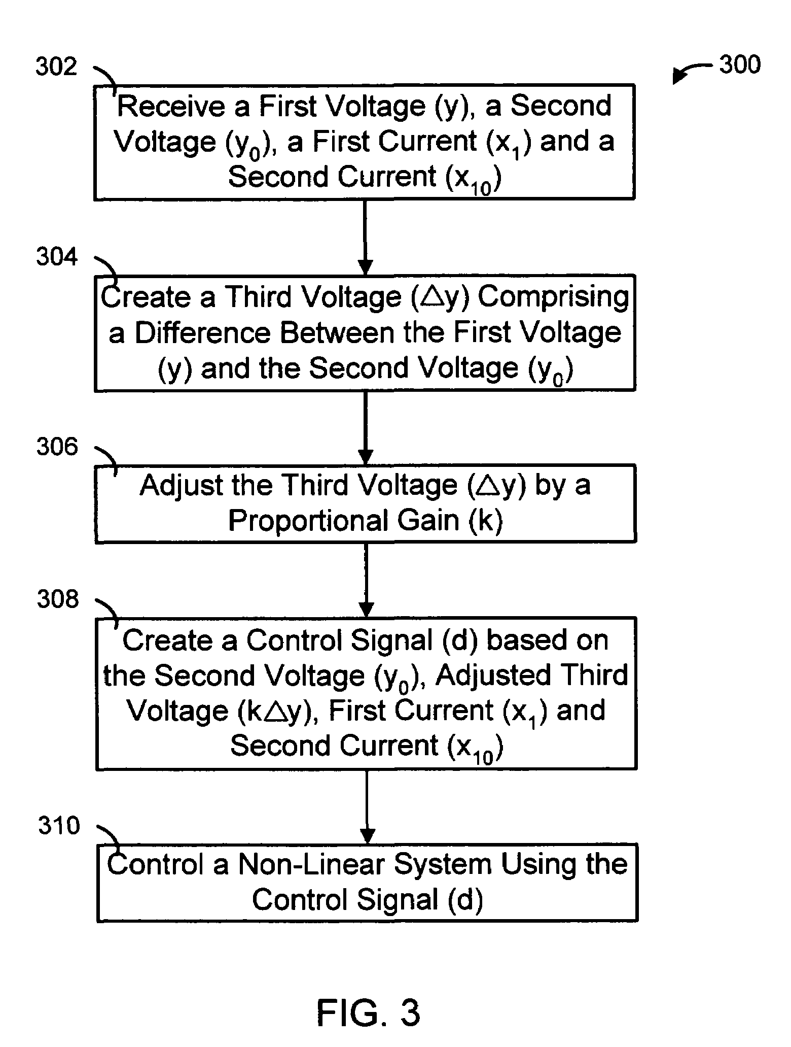
The present invention provides a system, method and apparatus for controlling any type of converter using input-output linearization and leading-edge modulation. The controller includes a summing circuit connected to the converter to create a third voltage representing a difference between the first voltage and the second voltage. A gain circuit is connected to the summing circuit to adjust the third voltage by a proportional gain. A modulating circuit is connected to the gain circuit, the converter, the second voltage and the second current to create a control signal based on the second voltage, the adjusted third voltage, the first current and the second current. The control signal is used to control the converter. Typically, the first voltage is an output voltage from the converter, the second voltage is a reference voltage, the first current is an inductor current from the converter and the second current is a reference current.

Description

FIELD OF THE INVENTION[0001]The present invention relates generally to providing modulation signals to electrical circuits and, more particularly, to a system, method and apparatus for controlling converters using input-output linearization and leading-edge modulation.BACKGROUND OF THE INVENTION[0002]Power converters are used to convert one form of energy to another (e.g., AC to AC, AC to DC, DC to AC, and DC to DC) thereby making it usable to the end equipment, such as computers, automobiles, electronics, telecommunications, space systems and satellites, and motors. Every application of power electronics involves some aspect of control. Converters are typically identified by their capability and / or configurations, such as, buck converters, boost converters, buck-boost converters, boost-buck converters (Ćuk), etc. For example, DC-DC converters belong to a family of converters known as “switching converters” or “switching regulators.” This family of converters is the most efficient b...

Claims


Application Information

Patent Timeline
Patent Type & Authority Patents(United States)
IPC IPC(8): G05F1/40
CPCH02M3/156
Inventor HUNT, LOUIS R.TAYLOR, ROBERT J.
Owner BOARD OF RGT THE UNIV OF TEXAS SYST
Learn More